background image


Содержание LS8000

Страница 1: ...MANUAL I IN NS ST TA AL LL LA AT TI IO ON N C CA AL LI IB BR RA AT TI IO ON N T TR RO OU UB BL LE ES SH HO OO OT TI IN NG G W WA AR RR RA AN NT TY Y TABLE OF CONTENTS Page 1 Description 1 BABBITT INTE...

Страница 2: ...tallation 2 A Inspection 2 B Physical Installation of Probe 2 C Installing the Receiver 3 D Typical Applications and Wiring Diagrams 4 1 LS8000 Terminal Layout 4 2 Ladder Diagrams 6 4 Calibration 10 A...

Страница 3: ...al Power 115 VAC 15 50 60 Hz 2 watts standard 12 VDC 24 VDC or 230 VAC optional Output 2 Form C contacts DPDT relay 5 amp resistive at 125 250 VAC 30 VDC Fuse On board 250 mA 125 volts Fail Safe Selec...

Страница 4: ...with probe attached 2 A transmitter module in the explosion proof enclosure 3 The LS8000 R receiver card 4 A plastic snaptrack to mount the receiver card B PHYSICAL INSTALLATION OF TRANSMITTER MODULE...

Страница 5: ...commend a 36 top mounted high level probe in storage silos and a 24 in smaller vessels such as use bins CAUTION Always take safety precautions before opening vessels for such inspection c On gravity f...

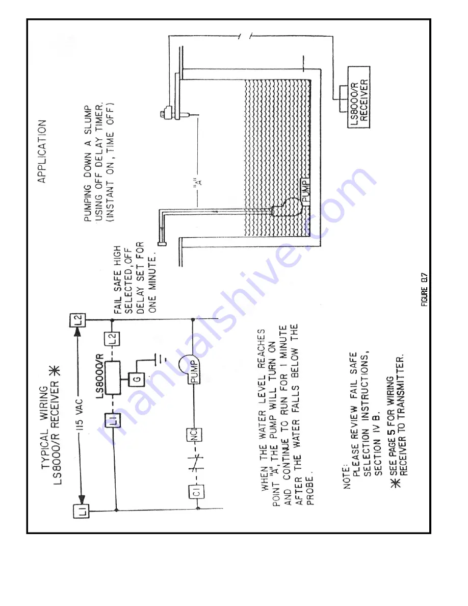
Страница 6: ...4...

Страница 7: ...5...

Страница 8: ...6...

Страница 9: ...7...

Страница 10: ...8...

Страница 11: ...9...

Страница 12: ...uching the probe The green led indicates relay status and is on when the relay is energized When product comes into contact with the probe the relay is de energized 2 Fail Safe Low FSL means that the...

Страница 13: ...o out replace electronics Check shielded cable for proper connection Check shielded cable for shorts or open circuits Unit triggers when material touches probe but will not reset when material recedes...

Страница 14: ...ditions or components which have been misused abused damaged by neglect or accident This warranty shall not apply to any components which have been altered or repaired without the prior written consen...

Отзывы: