background image

4

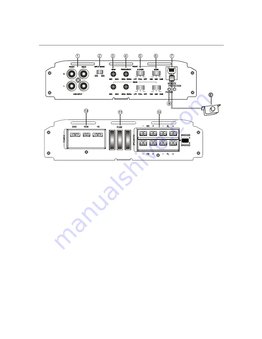
1. Low Level INPUT

RCA connector low level input connected to the speakers of the main unit.

2. High Level INPUT

Input connector plug connected to high-level speakers from the main unit.
NOTE: Do not connect cables high level input if you use the low level RCA input

3. Gain Adjustment (GAIN) 

Adjust to obtain the desired volume without distortion.

4. X-OVER: Cutoff Frequency Selector

Selector HPF (High Pass Filter) / LPF (Low Pass Filter) / FULL.

5. Cutoff frequency control X-OVER (50Hz-500Hz) 

Frequency selector for high pass and low pass.

6. Bass Boost (Bass Boost) 

Selectable 0dB / +6 dB / +12 dB

7. LED indicator

GREEN LED: Indicates normal amplifier operation
RED LED: Indicates the protection mode

8. Output for Remote Controller

Turn the gain (GAIN) to the maximum before using the remote control.
DESCRIPTION OF FUNCTIONS  

9. Remote Control

Gain adjustment from 0.2 V to +6 V

FEATURES AND DESCRIPTIONS

Содержание ELP 36.4

Страница 1: ...RUCTIONS MANUAL ELP 36 4 4 CHANNEL HIGH PERFORMANCE POWER AMPLIFIER Thank you for purchasing the amplifier 36 4 and your interest in products B52 Read this manual carefully before installing your new...

Страница 2: ...Before Installation 3 Features and Descriptions 4 Installation 5 Electrical diagram 6 Troubleshooting 8 Specifications 9 INDEX 2...

Страница 3: ...s for installation of 12V and negative grounding Before performing an installation in a van truck or bus check the battery voltage The black wire is the ground wire When installing this unit always co...

Страница 4: ...rtion 4 X OVER Cutoff Frequency Selector Selector HPF High Pass Filter LPF Low Pass Filter FULL 5 Cutoff frequency control X OVER 50Hz 500Hz Frequency selector for high pass and low pass 6 Bass Boost...

Страница 5: ...the chassis of the vehicle Note To prevent the ground wire GND to loosen or fall off the vehicle chassis you can install a screw and nut self braking 5 10 Fuse Holder Only replace fuses with same rat...

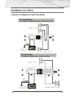
Страница 6: ...ELECTRICAL DIAGRAM a Configuration Diagram for 4 Channel Stereo 6...

Страница 7: ...ELECTRICAL DIAGRAM a Mode Setup diagram Bridge Bridge 7...

Страница 8: ...e the signal level on the main unit as much as possible and see if the hiss decreases Protection LED is activated when the amplifier is operating Check for a short circuit in the line of speakers Turn...

Страница 9: ...4 Signal to Noise Ratio 95dB THD 0 01 Channel Separation 1Khz 50dB Frequency Response 15Hz 30KHz Input Sensitivity 200mV 6V Input Impedance 15KOhm Minimum Speaker Impedance 2 Ohms Crossover Low Pass F...

Страница 10: ...www b52audio com NOTES...

Страница 11: ...ANALES Gracias por adquirir el Amplificador ELP 36 4 y por su especial inter s en los productos B52 Lea atentamente este manual de usuario antes de instalar su nuevo amplificador y cons rvelo en un es...

Страница 12: ...Antes de la Instalaci n 13 Descripci n de Funciones 14 Instalaci n 15 Diagrama El ctrico 16 Soluci n de Problemas 18 Especificaciones 19 INDICE 12...

Страница 13: ...de realizar una instalaci n en una camioneta cami n u mnibus compruebe el voltaje de la bater a El cable negro es el cable a tierra Cuando instale esta unidad siempre conecte primero el cable a tierra...

Страница 14: ...ra obtener el volumen deseado sin distorsi n 4 X OVER Selector de Frecuencia de Corte Selector HPF Filtro pasa Altos LPF Filtro pasa Bajos FULL 5 Control de Frecuencia de corte X OVER 50Hz 500Hz Selec...

Страница 15: ...tuerca auto frenante 15 10 Porta Fusible Reemplace el fusible solo por uno con la corriente y tensi n nominal indicada en las especificaciones 11 Terminales para conexi n de parlantes 12 GND Terminal...

Страница 16: ...DIAGRAMA ELECTRICO a Diagrama de Configuraci n para 4 Canales Est reo 16...

Страница 17: ...DIAGRAMA ELECTRICO b Diagrama de Configuraci n en Modo Puente Bridge 17...

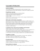
Страница 18: ...l en la unidad principal tanto como le sea posible y compruebe si el silbido disminuye La protecci n de led se activa cuando el amplificador est funcionando Verifique si existe un corto circuito en la...

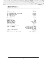
Страница 19: ...D 0 01 Separaci n de Canales 50dB Respuesta en Frecuencia 15Hz 30KHz Sensibilidad de Entrada 200mV 6V Impedancia de Entrada 15K Ohm Impedancia M nima para Parlantes 2 Ohms Divisor de Frecuencias Filtr...

Страница 20: ...www b52audio com NOTAS...

Страница 21: ...T NCIA 4 CANAIS Obrigado por adquirir o Amplificador ELP 36 4 e por seu interesse nos produtos B52 Leia com aten o este Manual do Usu rio antes de instalar seu novo amplificador e conserve o em espa o...

Страница 22: ...Antes da Instala o 23 Descri o de Fun es 24 Instala o 25 Diagrama El trico 26 Solu o de Problemas 28 Especifica es 29 INDICE 22...

Страница 23: ...ar uma instala o em caminhonetes caminh es ou nibus verifique a voltagem da bateria O cabo preto o cabo terra Sempre conecte primeiro o cabo terra ao instalar esta unidade Verifique se o cabo terra es...

Страница 24: ...ntrole para obter o volume desejado sem distor es 4 X OVER Seletor de Frequ ncia de Corte Seletor HPF Filtro passa altas LPF Filtro passa baixas FULL 5 Controle de Frequ ncia de corte X OVER 50Hz 500H...

Страница 25: ...m parafuso com porca autofrenante 25 10 Porta fus vel Trocar o fus vel somente por aqueles com corrente e tens o nominal informada nas especifica es 11 Terminais para conex o de alto falantes 12 GND T...

Страница 26: ...DIAGRAMA ELETRICO a Diagrama de Configura o para 4 Canais Est reo 26...

Страница 27: ...DIAGRAMA ELETRICO b Diagrama de Configura o no Modo Ponte Bridge 27...

Страница 28: ...tanto quanto for poss vel e confira se o chiado diminui A prote o de Led se ativa se o amplificador est em funcionamento Verifique a exist ncia de curtos circuitos na linha dos alto falantes Desligue...

Страница 29: ...0 01 Separa o de Canais 50dB Resposta em Frequ ncia 15Hz 30KHz Sensibilidade de Entrada 0 2V 6V Imped ncia de Entrada 15K Ohm Imped ncia M nima para Alto falantes 2 Ohms Divisor de Frequ ncias Filtro...

Страница 30: ...www b52audio com NOTAS...

Страница 31: ...MOBILE ENT E RTA INM E NT SY ST E M www b52audio com...

Отзывы: