I N S - P A F B 1 C _ E N I n s t r u c t i o n G u i d e : F r o n t B u m p e r
P a g e
9 | 12
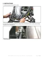
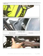
5.3 Position front bumper part 1 [P1] with a M6 X 25 mm hexagonal flanged screw [P3], M6 nylon lock nut [P5] and ground as shown.
Hand tighten only.
1- Ground located on LH side
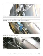
5.4 Secure front bumper part 1 [P1] with two (2) M6 X 25 rounded head screw [P4] and M6 washer [P6] using 6 mm Allen Key [T8].
TIGHTENING TORQUE
M6 X 25 rounded head screw [P4]
10 N•m ± 2 N•m


