B P L U S T V a . s .
MLA-T
page 2
MLA-T
There are three manual switch settings:
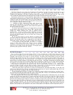
1). 1.8 MHz Band The external jumper adds one parallel capacitor
to the circuit as shown in Fig.2. The jumper on loop turn is removed,
Fig.3. The “gamma match” has the longest length.
2) 3.5 MHz Band The external jumper, Fig.2, is off. The jumper on
loop turn, Fig.3, is off. The “gamma match” at its shortest length.
3) 7 MHz Band The external jumper, Fig.2, is off, the jumper on
loop turn Fig.3, is on. The “gamma match” is at its shortest length.
B PLUS TV a. s., Po
ž
árnická 140, 742 83 Klimkovice, Czech Republic
phone: +420 556 420 360, fax: +420 556 420 301
e-mail: [email protected], http://www.btv.cz
Band Switching
First interconnect the transceiver, the control box with its power supply, and the remote MLA-T. Upon
setting the desired band, see Band Switching, Figs. 2 and 3, and setting the transceiver to the same band,
adjust receiver gains so that a noise can be heard. While in reception, push UP or DOWN push-buttons on the
Control box, and wait till you hear a noise peak or some useful signal. The noise burst is typically quite short;
you can return the variable capacitor, or wait till it turns by 180 degrees. Therefore, either push the other
button or keep pushing the same. After several trials you can hear the strongest band noise; then stop tuning.
After this adjustment in reception, you can continue with transmission. Adjust TX output of ~10 W and try to
improve the tuning by the SWR meter. The goal should be as close as possible to the ideal of 1:1. Due to the
high loop Q, mainly at 80-m band, the training will take some time. When the best tuning by SWR is finished,
Operation
increase the TX power to ~100W. Caution: with high humidity, the
antenna may not be able to handle full 100 W on 80 meters in all cases.
In this case internal discharges (arcing over) could occur within the
capacitor. This is indicated by jumping SWR while the power is
increased, but does not damage the antenna. Back off to keep the
SWR low.
To those not familiar with magnetic loop antennas, here are some
important points:
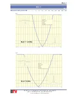
The horizontal radiation pattern of the MLA-T is shaped like number
eight, with a wide maximum and a sharp minimum. This is only valid
for the antenna in a vertical position (its plane normal to the earth's
surface). The depth of the minimum is very much affected by the
ambient environment (conductors around, even within walls), type of
wave propagation, the state of the ionosphere, i.e. the angle of wave
incidence on the antenna, etc., etc.
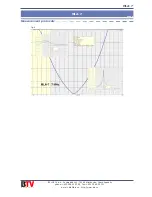
The vertical radiation pattern, with the loop plan is normal to
ground, can be seen in Fig.4. Magnetic loop antennas located low
above ground are ideal for NVIS ("Near Vertical Incidence Skywave",
for short range HF communication) wave propagation. This particular
feature of a MLA allows to effectively use ionospheric reflections over
short distances. Mostly useful in mountains.
fig.
2
fig.
3
fig.
4

