


Installation Instructions
JAMISON DOOR COMPANY
7
H4494002 REV B
•
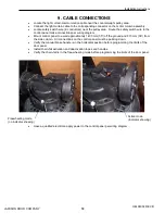
Locate the Drive Link Connectors in both side columns.
•
Remove the three (3) nuts and the Front Connector Plate from each connector (save all items for
Panel Assembly).
•
Verify the Drive Link Connectors are 235 mm or 9.25” from the top of the baseplate to bottom of
the connectors. Adjust if needed by moving the chain.
Verify:
235 mm (9.25”) from
top of baseplate to
bottom of connector.
Same dimension on
the Motor side and
the Counterweight
side.
Содержание ThermicRoll
Страница 2: ...Installation Instructions JAMISON DOOR COMPANY 2 H4494002 REV B...
Страница 14: ...Installation Instructions JAMISON DOOR COMPANY 14 H4494002 REV B Pin Set Screw Pin Set Screw...
Страница 27: ...Installation Instructions JAMISON DOOR COMPANY 27 H4494002 REV B 17 RADIO CONTROL RECEIVER...
Страница 38: ...Installation Instructions JAMISON DOOR COMPANY 38 H4494002 REV B Notes...