RELEASED
3-27-19
REFERENCE NUMBER
INS-2321-03
40429 Brickyard Drive • Madera, CA 93636 • USA
559.438.5800 • FAX 559.438.5900
www.bklighting.com • [email protected]
B-K LIGHTING
THIS DOCUMENT CONTAINS PROPRIETARY INFORMATION OF B-K LIGHTING, INC. AND ITS RECEIPT OR POSSESSION DOES NOT CONVEY ANY RIGHTS TO REPRODUCE, DISCLOSE ITS CONTENTS, OR TO MANUFACTURE, USE OR SELL ANYTHING IT MAY
DESCRIBE. REPRODUCTION, DISCLOSURE OR USE WITHOUT SPECIFIC WRITTEN AUTHORIZATION OF B-K LIGHTING, INC. IS STRICTLY FORBIDDEN.
IMPORTANT SAFETY INFORMATION - READ, FOLLOW, AND SAVE THESE INSTALLATION INSTRUCTIONS
Warning
Hot Surface
TOOLS
NEEDED:
By Others
5/64” & .050” Allen Wrench
Thermal Paste
11. Place cap on fixture and tighten three (3)
#8-32 set screws with 5/64” Allen wrench.
Top of screws should sit flush with fixture cap.
Warning: Do not over tighten set screw. Doing
so will compromise O-Ring seal and will void
warranty.
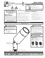
To Replace Module
1. Remove cap by loosening three (3) #8-32 set screws
using a 5/64” Allen wrench.
3. Loosen, then remove three (3) #2-28 screws from
optic module using .050” Allen wrench. Remove
optic holder from module.
5. Carefully remove LED module from heatsink, and
disconnect the quick disconnect from the LED
module.
Do not pull on connectors or wiring. Handle with
care.
4. Loosen and remove two (2) #4-40 screws holding
LED module to heatsink using 0.050” Allen wrench.
2. Gently twist optic to the left so optic tabs are clear
of optic holder and carefully pull away.
8. Secure LED module to heatsink with two (2) #4-40
screws.
7. Connect new LED module via quick disconnects.
Place new LED module onto heatsink, lining up
module with holes for screws.
10. Line up optic tabs in the optic holder, then gently
twist to the right to secure.
Module Replacement
DENALI SERIES™
Inspiration Control System
9. Tighten three (3) #2-28 screws on optic module using
.050” Allen wrench to secure optic holder.
6. Spread new thermal paste in even layer on
heatsink. Line up new LED board and place on
heatsink.


