background image

ICR-1601

5.6.3

Antenna Connector ANT, DIV and WiFi/GPS

The main and diversity antennas are connected to the router using the SMA connector on

the front panel. In the middle is located SMA connector for the WiFi resp. GPS antenna based
on the model. Only passive GPS antennas are supported.

The

ANT

connector is used to connect the main antenna to the router. To connect the

diversity antenna, the second antenna connector

DIV

is used.

The router can not operate without a main antenna connected through the port marked
as

ANT

!

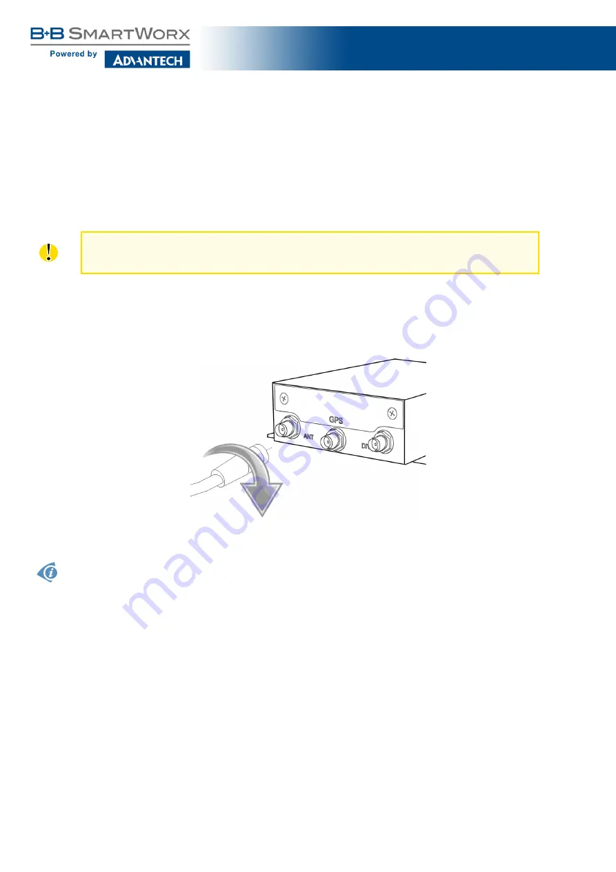
An SMA connector is used for the connection of the antenna. The antenna is connected

by screwing this antenna to the SMA connector on the front panel of the router (see figure
below). Recommended tightening moment is 0.9 Nm.

Figure 11: Connecting the antenna

A diversity antenna improves the radio capability of the router at low signal strength.

15

Содержание ICR-1601

Страница 1: ...LTE Industrial Router ICR 1601 USER MANUAL ...

Страница 2: ...onic or mechanical including photography recording or any information storage and retrieval system without written consent Information in this manual is subject to change without notice and does not represent a commitment on the part of Advantech B B SmartWorx Advantech B B SmartWorx s r o shall not be liable for incidental or consequential damages resulting from the furnishing performance or use ...

Страница 3: ...r information of special interest GPL licence Source codes under GPL licence are available free of charge by sending an email to techSupport advantech bb com Please see http ep advantech bb cz devzone for more information Advantech B B SmartWorx s r o Sokolska 71 562 04 Usti nad Orlici Czech Republic Document No MAN 0038 EN revision from August 29 2018 Released in the Czech Republic ii ...

Страница 4: ...e Router 10 5 4 1 Left view 10 5 4 2 Bottom view 10 5 5 Description of the Right Panel 11 5 6 Description of the Left Panel 12 5 6 1 Status Indication 13 5 6 2 Power Supply 14 5 6 3 Antenna Connector ANT DIV and WiFi GPS 15 5 6 4 SIM Card Reader 16 5 6 5 MicroSD Card Reader 17 5 6 6 Ethernet Ports 18 5 6 7 Factory Reset 19 5 7 Mounting recommendations 20 5 8 The DIN rail clip 21 6 First Use 23 6 1...

Страница 5: ...s 26 7 4 Type Tests and Environmental Conditions 26 7 5 Technical Parameters of Cellular Module 27 7 6 Technical Parameters of WiFi 28 8 Recommended Literature 29 9 Customers Support 30 9 1 Customer Support for NAM 30 9 2 Customer Support for Europe 30 9 3 Customer Support for Asia 30 iv ...

Страница 6: ...l 11 9 Left panel 12 10 Power adapter 14 11 Connecting the antenna 15 12 Installation of SIM cards 16 13 Installation of microSD memory card 17 14 Ethernet connector 18 15 Connection of Ethernet cable 18 16 Router reset 19 17 Installation of the DIN rail clips 21 18 Installation to the DIN rail 21 19 Removing from the DIN rail 22 20 The default IP address of the router 23 21 Entering login informa...

Страница 7: ... Order codes overview 8 3 LED status indication 13 4 Connection of Ethernet connector 18 5 Basic parameters 25 6 Technical specification of user interfaces 25 7 Standards and regulations 26 8 Technical parameters of cellular module 27 9 Technical parameters of WiFi 28 1 ...

Страница 8: ...outer against dust moisture and high temperature Only routers with appropriate certification and labelling should be used in locations where flammable and explosive materials are present including gas stations chemical plants or locations in which explosives are used We remind users of the duty to observe the restrictions concerning the utilization of radio devices at such places Switch off the ro...

Страница 9: ...r to minimize impact on the environment This product contains high quality materials and components which can be recycled At the end of it s life this pro duct MUST NOT be mixed with other commercial waste for disposal The device contains the battery Remove the battery from the device before disposal The battery in the device needs to be disposed apart accordingly Check the terms and conditions of...

Страница 10: ...Fi module or with GPS module This router is supplied in a metal bracket casing 3 3 Configuration and Diagnostics The ICR 1601 router can be configured using a password protected Web interface The web interface provides detailed statistics about the router activities signal strength detailed system logs etc This device supports the creation of VPN tunnels using technologies IPSec up to 3 tun nels O...

Страница 11: ...lities fleet management security systems telematics telemetric remote monitoring vending and dispatcher machines 3 4 Usage of the Router The router is primarily intended for these four basic situations I Access to the Internet from LAN Figure 1 Access to the Internet from LAN 5 ...

Страница 12: ...ICR 1601 II Backed up access to the Internet from LAN Figure 2 Backed up access to the Internet III Secure networks interconnection or using VPN Figure 3 Using a VPN tunnel 6 ...

Страница 13: ...tems listed in following table Item Description Figure Q ty 1 ICR 1601 router 1 pcs 2 Cellular antenna 2 pcs 3 WiFi antenna 1 pcs 4 Power adapter DC 5V 2A 1 pcs 5 DIN Rail bracket 1 set 6 Rubber feet 4 pcs 7 Printed Quick Start Guide 1 pcs Table 1 Contents of package 7 ...

Страница 14: ...TH GPS WiFi MicroSD ICR 1601 with GPS 2 x 2 x 1 x 1 x ICR 1601 with WiFi 2 x 2 x 1 x 1 x Table 1 Router versions 5 2 Order Codes The table below shows an overview of order codes Order code Features interfaces ICR 1601G LTE module Cat 4 2x ETH 1x USB 2x SIM 1x MicroSD GPS accessories ICR 1601W LTE module Cat 4 2x ETH 1x USB 2x SIM 1x MicroSD WIFI accessories Table 2 Order codes overview 8 ...

Страница 15: ...Product labels Product label is placed on the bottom of the router On pictures below are product labels for both GPS and WiFi versions Figure 4 Product label for GPS version Figure 5 Product label for WiFi version 9 ...

Страница 16: ...ICR 1601 5 4 Basic Dimensions of the Router 5 4 1 Left view Figure 6 Left view 5 4 2 Bottom view Figure 7 Bottom view 10 ...

Страница 17: ...he right panel is displayed on figure 8 Figure 8 Right panel The right panel contains LAN1 WAN RJ45 slot for LAN WAN connection see chapter 5 6 6 LAN2 RJ45 slot for LAN connection see chapter 5 6 6 PWR DC power receptacle plug see chapter 5 6 2 11 ...

Страница 18: ...ard SIM1 slot for the first SIM card see chapter 5 6 5 SIM2 slot for the second SIM card see chapter 5 6 4 Reset button for factory reset see chapter 5 6 7 ANT SMA connector for cellular antenna see chapter 5 6 3 WiFi GPS SMA connector for WiFi or GPS antenna based on model see chap ter 5 6 3 DIV SMA connector for diversity cellular antenna see chapter 5 6 3 12 ...

Страница 19: ...YS Blue Flashing 1x per 1 sec The router works normally Flashing fast The router is in recovery mode or in abnormal situration WAN Blue Purple Red When the color is Blue Cellular module is in LTE mode Purple Cellular module is in HSPA 3G mode Red Cellular module is in GSM 2G mode When the behavior of LED is Flashing fast 1x per 0 5 sec Signal strength is 0 30 Flashing slowly 1x per 1 sec Signal st...

Страница 20: ...ter is not determined for operating at wide temperature range environment For operation at full temperature range purchase other industrial power supply with required parameters Unit has to be supplied by a power supply specified as a Limited Power Source LPS ac cording to clause 2 5 of IEC UL 60950 1 or CEC NEC Class 2 source of supply as defined in the Canadian Electrical Code CSA C22 1 and Nati...

Страница 21: ...n antenna to the router To connect the diversity antenna the second antenna connector DIV is used The router can not operate without a main antenna connected through the port marked as ANT An SMA connector is used for the connection of the antenna The antenna is connected by screwing this antenna to the SMA connector on the front panel of the router see figure below Recommended tightening moment i...

Страница 22: ...nscrew two screws and remove the metal cover first Insert the SIM card by pushing it into the slot see figure below Push the inserted SIM card again to eject it from the slot Insert the metal cover back and screw it again In order for the router to function it is necessary to insert an activated SIM card with an unblocked PIN code The SIM cards may have different adjusted APNs Access Point Names F...

Страница 23: ...card is located on the left panel of the router protected by a metal cover It is necessary to unscrew two screws and remove the metal cover first Insert the microSD card by pushing it into the slot see figure below Push the inserted card again to eject it from the slot Insert the metal cover back and screw it again Supported are SDXC memory cards of class 10 with size from 64 GB to 2 TB Figure 13 ...

Страница 24: ...le below Pin Signal mark Description Data flow direction 1 TXD Transmit Data positive pole Input Output 2 TXD Transmit Data negative pole Input Output 3 RXD Receive Data positive pole Input Output 4 5 6 RXD Receive Data negative pole Input Output 7 8 Table 4 Connection of Ethernet connector Figure 14 Ethernet connector Plug the Ethernet cable into the RJ45 connector see the figure below Figure 15 ...

Страница 25: ...nd then release it After pressing this button the default factory configuration will be restored and the router will reboot It is necessary to use a narrow screwdriver or other small tool in order to press the Reset button Figure 16 Router reset All configuration settings will be set to their default states so it is recommended first to back up the router configuration settings see Configuration m...

Страница 26: ... a router on sheet steel we recommend using a cable antenna For all cables we recommend to bind the bunch and for this we recommend The length of the bunch combination of power supply and data cables should be a maximum 1 5 m If the length of data cables exceeds 1 5 m or if the cable is leading towards the switchboard we recommend installing surge protectors Data cables must not have a reticular t...

Страница 27: ...eep and TS 15 DIN rails On the picture below is described assembly of the two DIN rail clips to the router by four screews Figure 17 Installation of the DIN rail clips Installation of the DIN rail clip to the DIN rail of type TS 35 7 5 is illustrated on the picture bellow Figure 18 Installation to the DIN rail 21 ...

Страница 28: ...ICR 1601 In order to remove the DIN rail clip it is necessary to use a screewdriver as illustrated on following picture Figure 19 Removing from the DIN rail 22 ...

Страница 29: ...lt APN The DHCP server will start to assign addresses for devices connected through the Ethernet port ETH These router behaviors can be changed via the web interface This is described in detail in the Configuration manual for ICR 1601 2 6 2 1 Configuration by web browser For status monitoring configuration and administration of the router a web interface is available which can be accessed by enter...

Страница 30: ...d successfully the user will have access to the router s web interface via the web browser Figure 22 Router web interface A detailed description of the router settings in the Web interface can be found in the Configu ration manual for ICR 1601 2 24 ...

Страница 31: ... 95 relative humidity non condensing Supply voltage 5 to 18 V DC Consumption Maximum 7 W Dimensions 93 x 90 x 27 mm Antenna connectors 3x SMA 50 Ω Table 5 Basic parameters 7 2 Technical specification of user interfaces ETH Connector RJ45 Standard EN 1434 Min data rate 10 Mbps Max data rate 100 Mbps Max total cable length 300 Bd 200 nF km 100 m Table 6 Technical specification of user interfaces 25 ...

Страница 32: ...1 V11 1 1 ETSI EN 301 908 2 V11 1 1 ETSI EN 301 908 13 V11 1 1 ETSI EN 303 413 V1 1 1 ETSI EN 300 328 V2 1 1 EMC ETSI EN 301 489 1 V2 2 0 ETSI EN 301 489 19 V2 1 0 ETSI EN 301 489 52 V1 1 0 ETSI EN 301 489 17 V3 1 1 Safety EN 60950 1 EN 62368 1 EN 50385 EN 62311 Environmental RoHS Reach WEEE Table 7 Standards and regulations 7 4 Type Tests and Environmental Conditions TBD 26 ...

Страница 33: ...GPRS EDGE parameters GPRS bit rate 85 6 kbps DL 85 6 kbps UL EDGE bit rate 236 8 kbps DL 236 8 kbps UL GPRS multislot class 10 EDGE multislot class 12 Supported frequencies 900 MHz B8 1800 MHz B3 GSM900 transmit power 33 2 dBm GSM1800 transmit power 30 2 dBm Table 8 Technical parameters of cellular module Antenna Requirements VSWR 2 1 Antenna input impedance response as function of frequency This ...

Страница 34: ... SMA 50 Ω Supported WiFi band 2 4 GHz Standards 802 11n 802 11g 802 11b 2 4 GHz supported channels 1 2 3 4 5 6 7 8 9 10 11 12 13 Functions Multi SSID WMM Security WEP WPA WPA2 WPA PSK WPA2 PSK 802 1x Type of device Access point Table 9 Technical parameters of WiFi 28 ...

Страница 35: ...ture 1 Advantech B B SmartWorx Start Guide for ICR 1601 2 Advantech B B SmartWorx ICR 1601 Configuration Manual Product related documents and applications can be obtained on Engineering Portal at http ep advantech bb cz address 29 ...

Страница 36: ... m UTC 8 Fax 886 2 2794 7327 E mail icg support advantech com tw Web www advantech com Upkeep Advices The SIM card must be handled carefully as with a credit card Don t bend don t scratch on this and do not expose to static electricity During cleaning of the router do not use aggressive chemicals solvents and abrasive cleaners Hereby Advantech B B SmartWorx s r o company declares that the radio eq...

Отзывы: