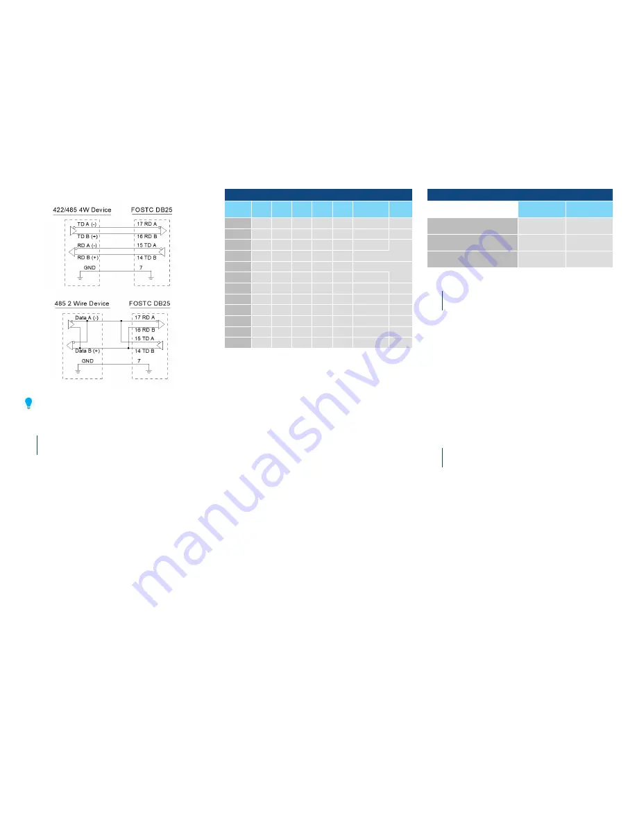
Before making modifications to the FOSTC, consult B+B SmartWorx’ free
“RS-422/485 Application Note” or other sources of information to see if
termination is necessary. Available at:
www.advantech-bb.com
RS-422 & RS-485 Connections - continued
RS-422/485 Connection Diagrams
DIP Switch Set Up
5
The Dip Switch (SW1) defines the mode of operation when
being used for RS-422 or RS-485.
Positions 1 through 5 determine the timeout of the RS-
485 driver. Because the driver is controlled by hardware, a
specific time
must be set
in order to tell the hardware how
long to wait for data on the fiber side before turning off the
RS-422/485 driver.
If this time is set too short, the driver could be disabled
before transmission is complete, resulting in data corruption.
If the time is set too long, the RS-485 device may respond
before the RS-422/485 driver in the FOSTC is disabled,
corrupting this response.
It is recommended that the timeout be set for approximately
one character time or longer. The character times for several
different baud rates are selectable on switch positions
1 through 5. If you need a different timeout than what is
provided, R10 can be removed and replaced with a different
value R9. Table 1 shows different timeout values for the
switch positions as well as typical R9 replacement values.
Position 6 of SW1 sets the unit in “Multidrop” mode or “Point-
to-Point” mode. See Figure 3 for typical system setups using
the FOSTC in different modes.
•
When set in
Multidrop Mode
, data arriving on the
fiber optic receiver is repeated back out the transmitter.
Position 6 must be turned “On” when the FOSTC is to
be used in a multi-drop ring configuration.
•
When set in
Point-to-Point Mode
, data arriving at
the fiber optic receiver is not sent back out the fiber
optictransmitter. Position 6 must be turned “Off” when
the FOSTC is to be used as either end of a point-to-
point communication line.
Positions 7 and 8 of SW1 determine when the RS-422/485
driver and receiver are enabled. Position 7 controls the
driver and Position 8 controls the receiver.
Table 2
illustrates
the switch settings for typical setups.
•
For
RS-485 two-wire systems
, both switches should
be in the “On” position. This disables the RS-422/485
receiver whenever the driver is enabled, preventing data
from being echoed back to the fiber side of the FOSTC.
•
For
multi-drop RS-485 four-wire systems
, position
7 should be “On” and position 8 should be “Off.” This
allows the receiver to be enabled all of the time and
eliminates some possible timing problems.
•
For
RS-422 operation
, set both switches to the “Off”
position.
Table 1. RS-485 Timeout Selection
BAUD
RATE
Pos.
1
Pos.
2
Pos.
3
Pos.
4
Pos.
5
R9
Time
(ms)
1200
ON
Off
Off
Off
Off
830 k
Ω
8.20
2400
ON
Off
Off
Off
Off
430 k
Ω
4.30
4800
Off
Off
Off
Off
ON
Not Used
2.20
9600
Off
Off
Off
ON
Off
Not Used
1.30
19.2k
Off
Off
ON
Off
Off
Not Used
0.56
38.4k
Off
ON
Off
Off
Off
Not Used
0.27
57.6k
ON
Off
Off
Off
Off
Not Used
0.22
76.8k
ON
Off
ON
ON
Off
Not Used
0.14
115.2k
ON
ON
ON
Off
Off
Not Used
0.10
153.3k
ON
Off
Off
Off
Off
6.3
k
Ω
0.06
230.4k
ON
Off
Off
Off
Off
4.3
k
Ω
0.04
460.8k
ON
Off
Off
Off
Off
2.2
k
Ω
0.02
Table 2. RS-422/485 Switch Settings
Position 8
TX Enable
Position 8
RX Enable
RS-485 2-Wire Mode
(half-duplex)
ON
ON
RS-485 4-Wire Mode
(full-duplex)
ON
Off
RS-422 Mode
(full-duplex)
Off
Off
Multi-Drop Operation
6
A multi-drop configuration is created by forming a ring of
FOSTCs (see Figure 1, Multi-drop Ring). Whichever serial
device sends data, all other devices receive it. The data is
repeated around the fiber ring until it reaches the source,
where it is blocked. There is no echo back to the serial side
of the sending device.
Each fiber transmitter must be connected to the following
converter’s receiver. Set SW1:6 to the “On” position on all
FOSTCs in the ring.
Any device can be full-duplex (RS-232, RS-422, or four-wire
RS-485) or half duplex RS-485. Because all data shares the
same path on the ring, only one device can send data at a
time.
Interfacing to Fiber Devices
from other manufacturers
7
NOTE: The factory default for the LED emitter is to have the
light “On” in the idle state. To interconnect with other devices
that have the light “Off” in the idle state, this unit would need
to be modified. To modify the unit so that the light is “Off” in
the idle state, contact B+B SmartWorx Technical Support.


