


-28-
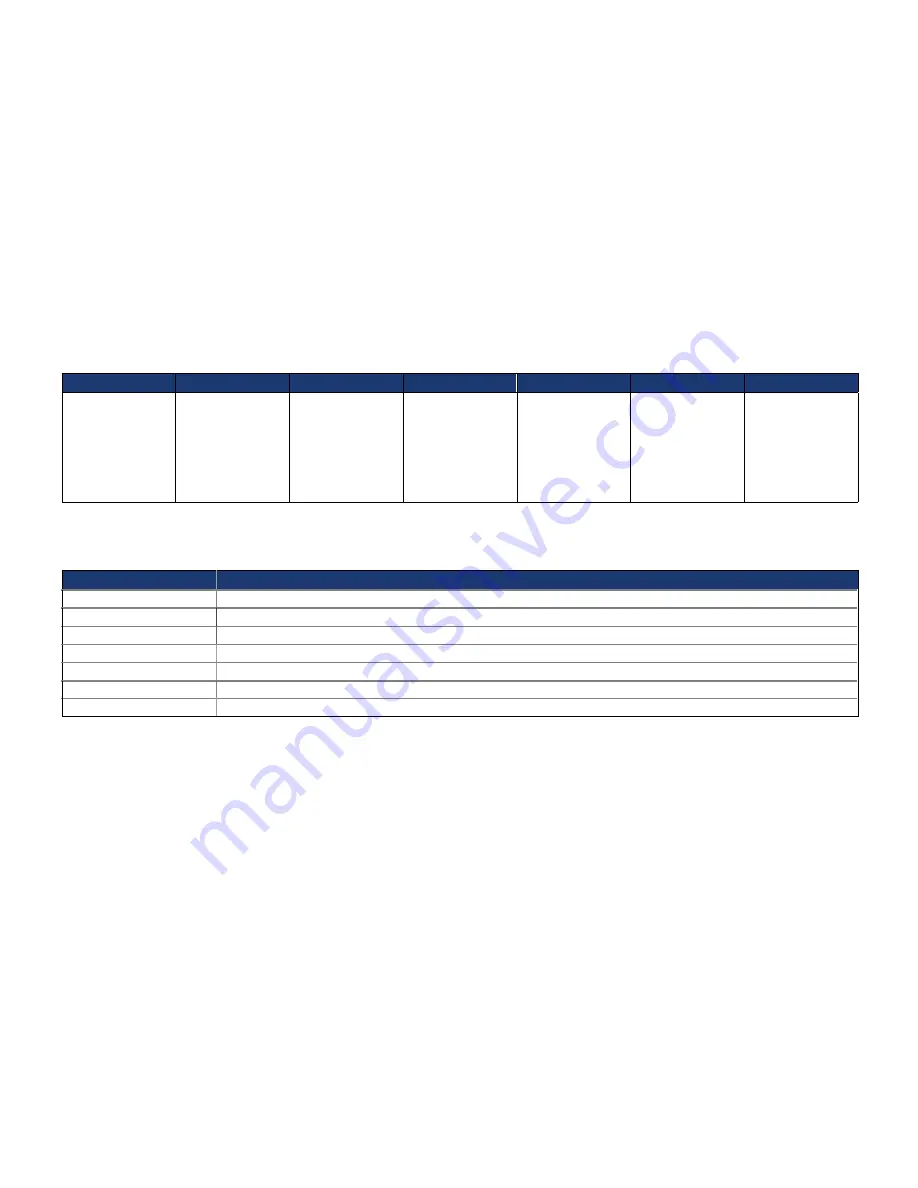
BIOS Setup Program Menu Bar
Maintenance
Main
Advanced
Security
Power
Boot
Exit
Clears
passwords and
displays
processor
information
Displays
processor
and memory
configuration
Configures
advanced
features
available
through the chipset
Sets
passwords
and security
features
Configures
power
management
features and
power supply
controls
Selects boot
options
Saves or
discards
changes to
Setup
program
options
Table 27 lists the function keys available for menu screens.
Table 27. BIOS Setup Program Function Keys
Key(s)
Description
←, →
Selects a different menu screen (Moves the cursor left or right)
↑, ↓
Selects an item (Moves the cursor up or down)
Tab
Selects a field (Not implemented)
Enter
Executes command or selects the submenu
F9
Load the default configuration values for the current menu
F10
Save the current values and exits the BIOS Setup program
Esc
Exits the menu
3-2. BIOS Flash Memory Organization
The Serial Peripheral Interface Flash Memory (SPI Flash) includes an 4 Mbit (512 KB) flash memory device.
Содержание P900 Series
Страница 1: ...Manuale POS serie 900 ...
Страница 2: ... 2 ...
Страница 11: ... 11 Package contents SlimPOS main unit Driver CD User manual Power cord ...
Страница 12: ... 12 Options Customer display ...
Страница 15: ... 15 Rear view Rear For Cable Management Customer Display Cover Rear Connectors Display Hinge ...
Страница 21: ... 21 Speaker and MIC connection 1 Speaker connection 2 MIC connection ...
Страница 22: ... 22 Printer connection Connect printer cable among Serial Parallel and USB port you required ...
Страница 40: ... 40 Chapter 5 Motherboard jumper setting 5 1 MotherboardLayout ...
Страница 43: ... 43 5 2 Diagram Diagram of the major functional areas The S Video connector is not available on the atom Board ...
Страница 47: ... 47 Rear cover change ...
Страница 48: ... 48 1 Loosen the screws by screwdriver 2 Pull up rear cover 3 Separate the rear cover Motherboard change ...
Страница 50: ... 50 4 Loosen the 4 screws 5 Remove the metal case cover 6 Loosen the 2 screws ...
Страница 51: ... 51 7 Remove the hinge cover 8 Loosen the 2 screws 9 Remove the part as shown ...
Страница 52: ... 52 10 Loosen the 6 screws 11 Remove the monitor hinge cover 12 Loosen the 12 screws ...
Страница 58: ... 58 Memory change 1 Open the release latches 2 Remove the memory ...
Страница 60: ... 60 Monitor change 1 Loosen the 2 screws 2 Remove the hinge cover 3 Loosen the 2 screws ...
Страница 61: ... 61 4 Remove the part as sharn 5 Loosen the 6 screws 6 Remove the monitor hinge cover ...
Страница 62: ... 62 7 Loosen the 12 screws 8 Disconnect the 3 monitor cable from motherboard 9 Replace monitor ...
Страница 66: ... 66 7 Loosen the 16 screws to separate LCD panel 8 Separate touch panel from LCD panel LCD touch panel ...


