background image

5

Assembly

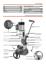
Please take some time to read the section entitled 
“Illustration and Parts Description” to identify the 
various parts of your machine so that you are familiar 
with the terminology we will use to enable you to set 
up and operate your Morticer safely and correctly.

Place the machine onto a suitable surface, at a height that 
will enable you to work comfortably and to ensure that 

there is adequate room on either side for the size of timber 
you plan to use. Once you are happy bolt the morticer 
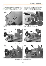
down. Loosen the locking caphead screw (a) to raise the 
morticers head assembly. Locate the operating lever (A) 
and the M6 x 16mm lift and shift handle (E), introduce the 
operating lever through the rack and pinion assembly, 
then secure the lever in place using the M6 lift and shift 
handle (E) (See fig 2).

Locate the operating wheel Shaft (C), remove the phillips 
screw, clamping washer and M6 x 23mm caphead screw 
and place them safely aside (See figs 3 and 5). Slide 
the machined cutout onto the transverse table shaft 

mechanism, line up the pre-drilled hole with the one in the 
table shaft mechanism and secure them in position using 
a 5mm allen key and the M6 x 23mm caphead screw you 
removed earlier (See figs 4 and 5).

Rack and pinion assembly

Remove the phillips screw  
and clamping washer.

Secure the wheel shaft (C) to the table 
shaft using the M6 caphead screw.

Slide the operating wheel (B) 
onto the operating shaft (C).

Locating 
key

Slot

Slide the machined cutout onto the 
transverse table shaft mechanism.

Table shaft 
mechanism

Fig 1.

Fig 3.

Fig 2.

Fig 4.

Fig 6.

A

C

C

B

E

a

Fig 5.

M6 Caphead 
screw

Содержание AC16BM

Страница 1: ...AC16BM Bench Morticer AT M 21 03 2019 BOOK REF 105799 Code 105114 Original Instructions ...

Страница 2: ...mbols below advise the correct safety procedures when using this machine Cert No MS3816 Axminster Tools Machinery Ltd Axminster Devon EX13 5PH UK axminster co uk Type Bench Morticer Model AC16BM and conforms to the machinery example for which the EC Type Examination Certificate No AN 50171993 AM 50171994 has been issued by LaizhouTongtailai Machinery Co Ltd at No 2666 Shuangfeng Road Chengguo Dong...

Страница 3: ...g Lever A 1 Saddle Operating Wheel B 1 Operating Wheel Shaft C 2 Distance Stop Rods D Bag 1 2 M6 x 30mm and M6 x 16mm Lift and Shift Handles E 2 Ring Collar Clamps with Lift and Shift Handles F Bag 2 1 13mm Chuck Key 6 5 3mm Allen Keys G 1 Instruction Manual A B C D E F G ...

Страница 4: ... should be given to the removal of rings and wristwatches Consideration should also be given to non slip footwear etc If another person is to use the machine ensure they are suitably qualified to use it Do not use the machine if you are tired or distracted Do not use this machine within the designated safety areas of flammable liquid stores or in areas where there may be volatile gases Check cutte...

Страница 5: ...h the rack and pinion assembly then secure the lever in place using the M6 lift and shift handle E See fig 2 Locate the operating wheel Shaft C remove the phillips screw clamping washer and M6 x 23mm caphead screw and place them safely aside See figs 3 and 5 Slide the machined cutout onto the transverse table shaft mechanism line up the pre drilled hole with the one in the table shaft mechanism an...

Страница 6: ...ighten by turning the lift and shift handle see fig 8 on the previous page Line up the countersink mark on the rod D with the grub screw make sure the grub screw is raised fully slide the rod D into the pre drilled hole to the end of casting and tighten the grub screw See figs 9 10 and 11 repeat for the opposite side Remove locking caphead screw a see page 5 that locks the morticers head assembly ...

Страница 7: ...tice depth stop Hollow chisel Distance stop assembly Table clamp assembly Worktable gib strip adjuster Crossfeed table control knob Transverse table control wheel Code 105114 Model AC16BM Rating Craft Power 375 W Voltage 230 V Chisel Stroke 100 mm Centre of Chisel to Back Fence 70 mm Max Height of Timber with 12 7mm Chisel and Bit 110 mm 160 mm with optional spacer block Max Chisel Size Softwood 1...

Страница 8: ...llustration and Parts Description Transverse gib strip adjusters Table gib strip adjusters Table fine feed control knob Auger mounting chuck Door catch Chuck door securing screw Lift and shift handle lock ...

Страница 9: ...on Operating lever Locking bolt Lift and shift handle lock Headbox support column Table Table clamping assembly Headbox gib strip adjusters Chuck access door Motor Base casting Fence Distance stop assembly Gas powered head return strut ...

Страница 10: ...lled hard down on the auger The penny was then removed and the chisel pushed up to the adaptor face and locked in place this established the one penny width between the chisel and the auger which for general timbers and mortice sizes is quite adequate Traditional morticers normally had a cross pin in the auger mounting mandrel to prevent the auger being pushed back up into the chisel The mounting ...

Страница 11: ... workpiece to be mortised at the depth you require Pull the headbox down and put the end of the timber against the chisel position the headbox so that the chisel points or the auger point are at the depth required raise the depth stop collar to the underside of the headbox and tighten gently Recheck the depth of the chisel point if it is satisfactory tighten securely if not it can be gently nudged...

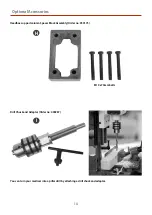
Страница 12: ...lts a that secures the support column YOU MAY REQUIRE ASSISTANCE AS THE HEADBOX SUPPORT COLUMN IS HEAVY Locate the spacer block H and the four M10 x 74mm bolts b line up holes in the spacer block H with the holes in the base casting place the headbox support column on top line up the holes and secure in position using the four M10 x 74mm bolts b washers spring washers and tighten using a 14mm span...

Страница 13: ...e holes in the table to prevent movement See figs 13 and 14 The clamp can also be pivoted to clamp uneven shapes See figs 17 and 18 The table has pre drilled holes which allows the clamp to be repositioned To the base of the clamp is a pin that slots into the centre holes in the table The table clamp can be adjusted to accommodate different sizes of timber The clamp can be pivoted to clamp uneven ...

Страница 14: ...essories Headbox support column Spacer Block Assembly Order no 950175 You can turn your morticer into a pillar drill by attaching a drill chuck and adaptor Drill Chuck and Adaptor Order no 400287 M10 x 74mm bolts H I ...

Страница 15: ... metal surfaces if the machine is going to stand idle for any length of time Keep the chisels and augers sharp Once a month Blow suck the motor to remove any debris that might have lodged in the fan cover Oil the chuck and exercise it over its full range to ensure the oil coats all moving parts There are full ranges of mortice chisels and a useful sharpening sets listed online at axminster co uk ...

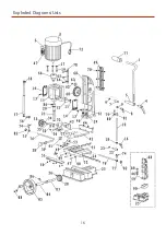
Страница 16: ...16 Exploded Diagrams Lists ...

Страница 17: ...r 2 37 Connecting Bend 1 38 Table Control Knob 1 39 Lead Screw 1 41 Lead Nut 1 42 Table 1 43 Clamp Plate 1 44 Screw 4 46 Spring Washer 2 47 Screw 3 Part No Description QTY 48 Nut 3 49 Handle Screw 2 50 Screw 6 51 Rack 1 52 Sliding Plate 1 53 Nut 2 54 Screw 2 55 Drift 1 56 Screw 1 57 Gas Spring 1 58 Screw 1 59 Washer 4 60 Gear 1 61 Bolt 4 62 Screw 1 63 Plate 1 64 Screw 3 65 Nut 2 66 Chuck 1 67 Swit...

Страница 18: ...18 Notes ...

Страница 19: ...19 Notes ...

Страница 20: ...together with household waste material By law they must be collected and recycled separately EU Countries Only The Axminster guarantee is available on Craft Trade Engineer AirTools CNCTechnology Series machines Buy with confidence from Axminster So sure are we of the quality we cover all parts and labour free of charge for three years For more information visit axminster co uk 3years ...

Отзывы: