background image

UST510-52B-FL Series u

ser’s Manual 


Hardware Installation 

9


SECTION 2 

HARDWARE INSTALLATION 

The UST510-52B-FL is convenient for various hardware configurations, such as CPU, DRAM, 

HDD (Hard Disk Drive), SSD (Solid State Drive), and PCI Express Mini card modules. Section 

2 contains guidelines for hardware installation. 


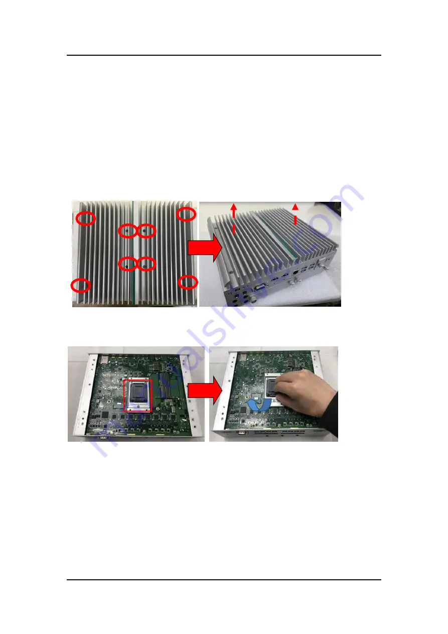
2.1   Installing CPU 

Step 1  Turn off the system and unplug the power cord. 

Step 2  Loosen all screws to remove the top cover. 


Step 3  Take the protective cover down carefully. 


Содержание UST510-52B-FL Series

Страница 1: ...UST510 52B FL Series Embedded System User s Manual...

Страница 2: ...r usefulness of any information in this document Axiomtek does not make any commitment to update any information in this manual Axiomtek reserves the right to change or revise this document and or pro...

Страница 3: ...ake sure the voltage of the power source is correct before connecting it to any power outlet 5 Turn OFF system power before cleaning Clean the system using a cloth only Do not spray any liquid cleaner...

Страница 4: ...n against electric shock not classified 2 Degree of protection against ingress of water IP40 3 Equipment not suitable for use in the presence of a flammable anesthetic mixture with air oxygen or nitro...

Страница 5: ...tention to components requiring designated products for cleaning as mentioned below Cloth A piece of cloth is the best tool to use when rubbing up a component Although paper towels or tissues can be u...

Страница 6: ...tek is a trademark of Axiomtek Co Ltd IBM PC AT PS 2 VGA are trademarks of International Business Machines Corporation Intel and Pentium are registered trademarks of Intel Corporation MS DOS Microsoft...

Страница 7: ...lling 2 5 SATA Device 15 2 4 1 Installing 2 5 SATA Device 15 2 5 Installing Mini PCIe M 2 Module 16 2 5 1 Installing Mini PCIe M 2 Module 16 2 6 Installing the Wall Mount Kit 19 2 6 1 Installing the W...

Страница 8: ...12 M 2 Key E Connector CN18 28 3 2 13 M 2 3050 3052 Key B CN14 29 SECTION 4 BIOS SETUP UTILITY 31 4 1 Starting 31 4 2 Navigation Keys 32 4 3 Main Menu 33 4 4 Advanced Menu 34 4 5 Chipset Menu 52 4 6...

Страница 9: ...and comes with flexible I O design To fulfill different application needs the flexible embedded system supports WE8S WES7 Windows 10 and Linux and can be wall mounted or DIN rail mounted as an option...

Страница 10: ...lexibility and multi functional design to present the best solution for any industrial field applications Flexible Connectivity The UST510 52B FL comes with rich I O interfaces including two RS 232 42...

Страница 11: ...nnection and electric power to devices eg IP camera Note The UST510 is a power supply device Two PSE devices should not be connected together which may cause the risk of power conflict Correctly conne...

Страница 12: ...ation Temperature 40 C 60 C 40 F 158 F with W T SSD Memory Coffee Lake Operating environment varies depending on the CPU model in use Storage Temperature 40 C 85 C 40 F 185 F Humidity 10 95 non conden...

Страница 13: ...UST510 52B FL Series user s Manual Introduction 5 1 3 Dimensions The following diagrams show the dimensions and outlines of the UST510 52B FL 1 3 1 UST510 52B FL Dimensions...

Страница 14: ...UST510 52B FL Series user s Manual 6 Introduction 1 4 I O Outlets The following figures show I O outlets on the UST510 52B FL Front View Rear View...

Страница 15: ...4 Mini Card slot screws x 4 M 2 key A E 2230 size slot screw x 1 M 2 Key B 3050 3052 size slot screw holder x 1 Audio cable fixture x 1 option HDMI cable fixture x 2 option 1 6 Model List UST510 52B F...

Страница 16: ...UST510 52B FL Series user s Manual 8 Introduction This page is intentionally left blank...

Страница 17: ...dware configurations such as CPU DRAM HDD Hard Disk Drive SSD Solid State Drive and PCI Express Mini card modules Section 2 contains guidelines for hardware installation 2 1 Installing CPU Step 1 Turn...

Страница 18: ...he processor which aligns with connection 1 indicator chamfer on the socket and notice processor keying features that line up with posts along socket walls Grasp the processor with the thumb and index...

Страница 19: ...ey on the socket Step 4 And apply the thermal pad on top of the processor Step 6 Put the top cover back onto the system and fasten all screws Note When removing the top cover to change accessories the...

Страница 20: ...rdware Installation 2 2 Installing SO DIMM Step 1 Turn off the system and unplug the power cord Step 2 Loosen all screws to remove the top cover Step 3 Locate the dual SO DIMM sockets on the main boar...

Страница 21: ...p 5 Insert the gold colored contact of the memory module into the socket and push the module s two end latches down until the module is locked in place Put the thermal pad on the DDR module again Step...

Страница 22: ...g thermal pads Step 1 Turn off the system and unplug the power cord Step 2 Loosen all screws to remove the top cover Step 3 Put the thermal pads on the secant locations Note It is suggested that the t...

Страница 23: ...all of the SATA drive tray s screws Step 3 Extract the SATA drive tray One drive tray can be used to install two SSD HDD drives Step 4 Turn the SATA drive tray upside down to install SSD HDD and fast...

Страница 24: ...1 Turn off the system and unplug the power cord Step 2 Turn the system upside down and loosen the SATA trays Step 3 Extract both SATA trays as shown Step 4 Loosen all screws and open the bottom cover...

Страница 25: ...on 17 Step 7 Insert the M 2 3050 3052 B key card and fasten the screws as shown Step 8 Place the cover back onto the bottom of the system and fasten all screws firmly Step 9 Slide the SATA trays back...

Страница 26: ...UST510 52B FL Series user s Manual 18 Hardware Installation...

Страница 27: ...Mount Kit 2 6 1 Installing the Wall Mount Kit Step 1 Turn off the system and unplug the power cord Step 2 Locate the wall mount screw holes on both sides of the system Step 3 Attach the wall mount to...

Страница 28: ...s shown below Step 3 Insert the HDMI cable into the system s HDMI port Then Insert a cable tie through the loop of the cable fixing plate to bind the HDMI cable to the plate as shown below 2 7 2 Audio...

Страница 29: ...tate of the UST510 52B FL Note Refer to APPENDIX C for instructions on power button settings for Windows Functions Descriptions On Turn on off system Off Keep system status 3 1 2 Reset Button The rese...

Страница 30: ...D 3 ACC Accessory Power Figure 1 Note Connect the DC in power connector for the UST510 52B FL in vehicle system as follows When using in vehicle applications connect the ACC pin to the accessory power...

Страница 31: ...video and high resolution audio over a single cable Pin definition follows HDMI Type A standard 3 2 3 Serial Port Connector COM1 COM2 1 port TB supports 2COM COM mode supports RS 232 422 485 which can...

Страница 32: ...Signal L1 MDI0 L5 MDI2 L2 MDI0 L6 MDI2 L3 MDI1 L7 MDI3 L4 MDI1 L8 MDI3 A Activity link LED Yellow OFF No link Blinking Link established data activity detected B Speed LED OFF 10Mbps data rate Green 10...

Страница 33: ...n 2 Line Out 3 2 7 Digital I O The UST510 52B FL supports 6CH isolated digital inputs and 2CH isolated digital outputs Pins Signals Pins Signals 1 COM 7 IN 0 2 OUT0 8 IN 1 3 OUT1 9 IN 2 4 COM 10 IN 3...

Страница 34: ...gnals PCI Express complies with PCI Express Mini Card Spec V1 2 Thus users can install an mSATA or WLAN WWAN card into this slot Please refer to the SATA of BIOS setting to enable or disable mSATA sup...

Страница 35: ...stall an mSATA card into this slot Pins Signals Pins Signals 51 NC 52 3 3Vaux 49 NC 50 GND 47 NC 48 1 5V 45 NC 46 NC 43 GND 44 NC 41 3 3Vaux 42 NC 39 3 3Vaux 40 GND 37 GND 38 USB_D 35 GND 36 USB_D 33...

Страница 36: ...D 22 CNV_BRI_RSP 21 CNV_WR_CLK_DN 23 CNV_WR_CLK_DP 32 CNV_RGI_DT 34 CNV_RGI_RSP 33 GND 36 CNV_BRI_DT 35 PCIE12_TX_DP 38 CL_RST 37 PCIE12_TX_DN 40 CL_DATA 39 GND 42 CL_CLK 41 PCIE12_RX_DP 44 CNV_PA_BLA...

Страница 37: ...Key B 17 Key B 18 Key B 19 Key B 20 GPIO_5 21 CONFIG_0 22 GPIO_6 23 GPIO_11 24 GPIO_7 25 DPR 26 GPIO_10 27 GND 28 GPIO_8 29 USB3 1 Tx 30 UIM RESET 31 USB3 1 Tx 32 UIM CLK O 33 GND 34 UIM DATA I O 35 U...

Страница 38: ...UST510 52B FL Series user s Manual 30 Button Connector Settings 69 CONFIG_1 70 3 3V 71 GND 72 3 3V 73 GND 74 3 3V 75 CONFIG_2...

Страница 39: ...creens follow the steps below 1 Turn on the computer and press the Del key immediately 2 After pressing the Del key the main BIOS setup menu displays Users can access to other setup screens such as th...

Страница 40: ...n Plus Minus The Plus and Minus Arrow keys allow users to change the field value of a particular setup item Tab The Tab key allows users to select setup fields F1 The F1 key allows users to display th...

Страница 41: ...creen is also shown below BIOS Information Display the auto detected BIOS information System Language Choose the system default language System Date Time Use this option to change the system time and...

Страница 42: ...devices Users can select any items in the left frame of the screen to go to sub menus MiniCard Switch CPU Configuration NCT6106D HW Monitor NCT6106D Super IO Configuration SATA And RST Configuration...

Страница 43: ...UST510 52B FL Series user s Manual BIOS Setup Utility 35 Mini Card switch Use this to select Mini Card setting default is PCIE...

Страница 44: ...onfiguration This screen shows the CPU version and its detailed information Intel Virtualization Technology It allows a hardware platform to run multiple operating systems separately and simultaneousl...

Страница 45: ...tion A description of the selected item appears on the right side of the screen For items marked with press Enter for more options The default setting for all Serial Ports is RS232 You can change the...

Страница 46: ...UST510 52B FL Series user s Manual 38 BIOS Setup Utility Serial Port 1 2 Configuration...

Страница 47: ...UST510 52B FL Series user s Manual BIOS Setup Utility 39 Select Mode Use this option to set RS 232 RS 422 RS 485 mode...

Страница 48: ...UST510 52B FL Series user s Manual 40 BIOS Setup Utility NCT6106D Hardware Monitor This screen displays the temperatures of system and CPU and system voltages VCORE 3 3V 12V and 5V...

Страница 49: ...r s Manual BIOS Setup Utility 41 SATA RST Configuration SATA Mode Selection AHCI Advanced Host Controller Interface mode is how SATA controller s operate Serial ATA Port 0 3 It shows the device instal...

Страница 50: ...usted Computing This sub menu will allow you to enable disable Trusted Platform Module TPM support and to configure the TPM State Select Trusted Computing and press Enter to access the sub menu Select...

Страница 51: ...UST510 52B FL Series user s Manual BIOS Setup Utility 43 USB Configuration This screen specifies USB settings USB Devices Display all detected USB devices...

Страница 52: ...s Manual 44 BIOS Setup Utility Device Configuration The DIO Modification default setting is disable If the setting is changed to enable you can load manufacture default and program DIO setting Please...

Страница 53: ...UST510 52B FL Series user s Manual BIOS Setup Utility 45...

Страница 54: ...UST510 52B FL Series user s Manual 46 BIOS Setup Utility...

Страница 55: ...ted based on the 24 hour military time clock BIOS menu item Description Ignition Management Enabled Switch to In Vehicle mode Disabled Switch to AT Railway mode PSU and system will reset after setting...

Страница 56: ...prevented the system from properly powering on off BIOS menu item Description Activate Voltage Trigger The system only turns on when the voltage delivered by the power source is higher than the value...

Страница 57: ...The counter will be reset if IGN is off and on during the system countdown time Shutdown Delay Timer IGN Off When the system is on IGN voltage goes off and the system will be gracefully shut down by...

Страница 58: ...electricity to the PD Please request the PD supplier for clear Power Classifications watts values or checking the info in the BIOS Set Power Budget Set disconnection power level for a specific power M...

Страница 59: ...UST510 52B FL Series user s Manual BIOS Setup Utility 51 Port1 Port8 Enable Disable a specific POE port and display all port status...

Страница 60: ...u The Chipset menu allows users to change the advanced chipset settings Users can select any of the items in the left frame of the screen to go to the sub menus System Agent SA Configurations PCH IO C...

Страница 61: ...UST510 52B FL Series user s Manual BIOS Setup Utility 53 System Agent SA Configurations...

Страница 62: ...UST510 52B FL Series user s Manual 54 BIOS Setup Utility Memory Configuration Use this item to refer to the information related to system memory This screen shows the system memory information...

Страница 63: ...UST510 52B FL Series user s Manual BIOS Setup Utility 55 PCH IO Configuration This screen shows ME Firmware information...

Страница 64: ...S Setup Utility Security Menu Administrator Password This item indicates whether an administrator password has been set installed or uninstalled User Password This item indicates whether a user passwo...

Страница 65: ...l BIOS Setup Utility 57 4 6 Boot Menu The Boot menu allows users to change boot options of the system providing UEFI Legacy and Compatible modes to select from The default setting boot mode is UEFI Mo...

Страница 66: ...r of seconds to wait for setup activation key where 65535 0xFFFF means indefinite waiting Bootup NumLock State Use this item to select the power on state for the keyboard NumLock Boot Option Prioritie...

Страница 67: ...tup Utility 59 4 7 Save Exit Menu The Save Exit menu allows users to determine whether or not to accept their modifications to the system configuration or to keep default values for optimal fail safe...

Страница 68: ...tion and reboot the computer Select Discard Changes and Reset from the Save Exit menu and press Enter Select Yes to discard changes and reset Save Changes After completing the system configuration cha...

Страница 69: ...How to Use the Watchdog Timer The user can configure the watchdog timer using the watchdog function included in the AXVIEW2 0 software developed by Axiomtek or using the debug exe software released by...

Страница 70: ...watchdog timer STEP Sample code Note 1 Enter configuration mode O 2E 87 O 2E 87 Un lock super I O Un lock super I O 2 Select logic device O 2E 07 O 2F 08 Select logic register Switch to WDT device 3 D...

Страница 71: ...utput current 200mA max per channel on state voltage 12 24VDC nominal Isolation 3 75 KV Max voltage on COM 30VDC Digital I O DIO LED Software Programming Digital I O and LEDs are controlled by General...

Страница 72: ...UST510 52B FL Series user s Manual 64 Digital I O...

Страница 73: ...UST510 52B FL Series user s Manual Digital I O 65 Digital Input Wiring...

Страница 74: ...UST510 52B FL Series user s Manual 66 Digital I O Digital Output Wiring...

Страница 75: ...ries user s Manual Power Button Setting For Windows 67 APPENDIX C POWER BUTTON SETTING FOR WINDOWS To enable the power button function go to the console of the PC and then follow below figures to comp...

Страница 76: ...ST510 52B FL Series user s Manual 68 Power Button Setting For Windows Please check if the action of pressing the power button is Shut down to let ACC work normally and prevent unexpected hard shut dow...

Страница 77: ...UST510 52B FL Series user s Manual Power Button Setting For Windows 69...

Отзывы: