background image

NA580  Series  User

’s  Manual 

Hardware  and  Installation


23


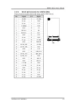
2.4.14 

Mini Card Connector for mSATA (CN4) 

This is a 52-pin connector which is commonly used for mSATA device. 


51

52

18

17

2

1


CN4 


Pin 

Signal 

Pin 

Signal 

WAKE# 

+3.3VSB 

No use 

GND 

No use 

+1.5V 

CLKREQ# 

PWR 

GND 

10 

I/O 

11 

REFCLK- 

12 

CLK 

13 


14 

RST 

15 

GND 

16 

VPP 

17 

No use 

18 

GND 

19 

No use 

20 

+3.3VSB 

21 

GND 

22 

PERST# 

23 

SATA0_RXP 

24 

+3.3VSB 

25 

SATA0_RXN 

26 

GND 

27 

GND 

28 

+1.5V 

29 

GND 

30 

SMB_CLK 

31 

SATA0_TXN 

32 

SMB_DATA 

33 

SATA0_TXP 

34 

GND 

35 

GND 

36 

USB_D- 

37 

GND 

38 

USB_D+ 

39 

+3.3VSB 

40 

GND 

41 

+3.3VSB 

42 

No use 

43 

GND 

44 

No use 

45 

No use 

46 

No use 

47 

No use 

48 

+1.5V 

49 

No use 

50 

GND 

51 

No use 

52 

+3.3VSB 

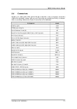
Содержание NA580 series

Страница 1: ...NA580 Series SMB Network Appliance User s Manual ...

Страница 2: ...anual Axiomtek reserves the right to change or revise this document and or product at any time without notice No part of this document may be reproduced stored in a retrieval system or transmitted in any form or by any means electronic mechanical photocopying recording or otherwise without the prior written permission of Axiomtek Co Ltd CAUTION If you replace wrong batteries it causes the danger o...

Страница 3: ... However there is no guarantee that interference will not occur in a particular installation If this equipment does cause harmful interference to radio or television reception which can be determined by turning the equipment off and on the user is encouraged to try to correct the interference by one or more of the following measurers Reorient or relocate the receiving antenna Increase the separati...

Страница 4: ...ed technician is allowed to do so Integrated circuits on computer boards are sensitive to static electricity To avoid damaging chips from electrostatic discharge observe the following precautions Before handling a board or integrated circuit touch an unpainted portion of the system unit chassis for a few seconds This will help to discharge any static electricity on your body When handling boards a...

Страница 5: ... Power Button Model Jumper JP6 14 2 3 4 TACT SW1 Function Selection Jumper JP8 14 2 4 Connectors 15 2 4 1 LCM Connector LCM1 16 2 4 2 TPM Module Connector TPM1 16 2 4 3 Front Panel Bezel Connector JP7 17 2 4 4 Serial Port1 USB3 0 Port1 2 Connector CN10 18 2 4 5 ATX Power Connector CN1 18 2 4 6 ATX 12V CPU Power Connector ATX1 19 2 4 7 Serial ATA Connectors SATA1 2 3 4 19 2 4 8 USB Port Connectors ...

Страница 6: ...tion Keys 29 3 3 Main Menu 30 3 4 Advanced Menu 31 3 5 Chipset Menu 45 3 6 Security Menu 48 3 7 Boot Menu 49 3 8 Save Exit Menu 50 Appendix A LAN Bypass Configuration 55 About LAN Bypass 55 LAN Bypass Register Configuration 56 Appendix B WDT Timer for System Reset 59 Appendix C LAN Module Expansion 61 LAN Bypass Control Jumper JP2 JP3 61 Appendix D Warning 69 ...

Страница 7: ...e LAN module via the PCIe 3 0 interface support max up to 18 LAN ports To avoid the influences of shutdown by the environment the NA580 s motherboard supports data protection via 2 pairs of latch type LAN bypass for fail over option For storing event log data the NA580 utilizes two 2 5 SATA HDDs or one 3 5 SATA HDD And NA580 supports four dual channel up to 64GB DDR4 2400 non ECC ECC memory and on...

Страница 8: ...0 DIMM sockets up to 64GB none buffer none ECC ECC memory NA580 PCH H110 2 x DDR4 2400 DIMM sockets up to 32GB none buffer none ECC memory BIOS AMI 128Mbit PnP Flash BIOS with function of BIOS redirected to COM port HDD Interface Two 2 5 SATA HDDs or one 3 5 SATA HDD optional LAN The default is 8 x 10 100 1000Mbps LAN ports and 2 pairs LAN bypass NA580 Expandable up to 18 LAN ports via LAN modules...

Страница 9: ...RS 232 one is 10 pin header onboard but RX TX signal is co lay used for LCM module connector the other one is RJ type connector with Cisco define I O Interface One console RJ type connector 2 x USB 3 0 connectors and 8 x RJ 45 connectors default or up to 18 LAN ports expandable LED 1x4 LED for LAN bypass 1 2 Power and HDD 1x2 LED for GPO 1 2 1 x LAN modules optional Tact switch x2 up GPI button do...

Страница 10: ...0W single power supply 1U 280W redundant power supply 1 1 optional Note Indicates to unplug all AC power cord s to disconnect AC Power OS Compatibility Linux 2 6 x 3 x Mechanical Environmental Form Factor 1U rackmount LED Power HDD GPIO LEDs LAN bypass LEDs Operation Temperature 0 C 45 C 32 F 113 F ATX Power Supply 0 C 40 C 32 F 104 F Redundant Power Supply Storage Temperature 20 C 85 C 4 F 185 F ...

Страница 11: ...NA580 Series User s Manual Introduction 5 1 4 Dimensions and Outlines The following diagram shows you dimensions and outlines of the NA580 Series Default 8 LAN ports max up to 18 LAN ports ...

Страница 12: ... be found in the CD and they are only for customers reference as remarked Default Tact Switch The sample code will be provided that allows users to define their own function For example when the system has any problems this switch can support to reset it to the customer s OS default settings if our customer s OS supports this application Reset Tact Switch It is for reset the system to reboot your ...

Страница 13: ...n the green color LED light is radiating the transfer rate should be 100Mbps When the orange color LED light is radiating the transfer rate should be 1000Mbps When this LED and Link Active LED both are dark no networking devices are attached Active Link LED for LAN Port The orange LED is on when the LAN port connection is working The LED flashes when transmitting or receiving any signals to or fro...

Страница 14: ...Series User s Manual 8 Introduction 1 5 2 Rear Panel Power Supply System power use power cord to connect the power supply to electrical outlet AC System Fans These are fans for cooling down system temperature ...

Страница 15: ...es network appliance hardware platform Power cord x 1 Utility CD including user s manual and sample code Mounting brackets for rack installation left right x 2 Plastic stand for stack up x 4 Mounting screws for disk drive and additional screws for this appliance s spare parts SATA cable x 2 for 2 5 SATA HDDs If you can not find this package or any items are missing please contact Axiomtek distribu...

Страница 16: ...NA580 Series User s Manual 10 Hardware and Installation 2 2 Board Layout TOP ...

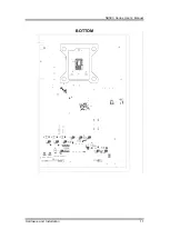
Страница 17: ...NA580 Series User s Manual Hardware and Installation 11 BOTTOM ...

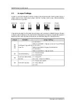
Страница 18: ...he main board in this appliance to meet your application purpose Below we list a summary table of all jumpers and default settings for onboard devices Jumper Definition Jumper Setting JP1 JP2 JP3 LAN Bypass Trigger When Power On 1 2 1 2 1 2 Mother board SEGN1 2 Bypass as same as Power Off status 1 2 1 2 2 3 Mother board SEGN1 2 Bypass Disable Default 1 2 2 3 2 3 Mother board SEGN1 2 Bypass Enable ...

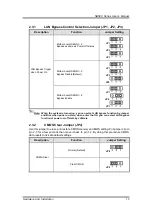
Страница 19: ...Enable JP1 JP2 JP3 Note When the system is turned on you can select LAN bypass function by Jumper and Bios when power on state when enter the OS you can select LAN bypass function at power on off state by software 2 3 2 CMOS Clear Jumper JP4 Use this jumper to erase and restore CMOS memory and BIOS setting Put jumper clip to pin 2 3 for a few seconds then move it back to pin 1 2 By doing this proc...

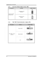
Страница 20: ...umper JP6 Description Function Jumper Setting Auto Power Button Mode Selection Always Power Off ATX Mode JP6 Always Power On Default JP6 2 3 4 TACT SW1 Function Selection Jumper JP8 Description Function Jumper Setting TACT SW1 Function Selection Power On Off JP8 Reset Default JP8 GPI JP8 ...

Страница 21: ... Console USB3 0 Port0 Port1 Connector CN10 ATX Power Connector CN1 ATX 12V CPU Power Connector ATX1 Battery Connector BAT1 LAN1 LAN2 LAN3 LAN4 RJ45 Connector CN13 LAN5 LAN6 LAN7 LAN8 RJ45 Connector CN14 VGA Connector VGA1 Serial Port2 Connector COM2 FAN Connector FAN1 3 Serial ATA Connector SATA1 4 Front Switch Panel Connector SW1 GPIO Connector reserved CN3 Mini Card Connector CN6 Mini Card Conne...

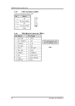
Страница 22: ...CM Pin Signal LCM1 1 5V 2 RX colay COM2 3 N C 4 TX colay COM2 5 GND 2 4 2 TPM Module Connector TPM1 Pin Signal Pin Signal 1 2 19 20 TPM1 1 CLK_33M 2 GND 3 LPC_FRAME 4 N C 5 PLTRST 6 5V 7 LPC_AD3 8 N C 9 3 3V 10 LPC_AD1 11 LPC_AD0 12 GND 13 SMBCLK 14 SMBDATA 15 N C 16 SUS_STAT 17 GND 18 LPC_SERIRQ 19 SUSCLK 20 N C ...

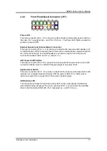
Страница 23: ...need to set pins 2 4 to Open and connect the speaker cable to pin 8 and pin 2 ATX Power On Off Button This 2 pin connector Pin 9 10 connects the front panel s ATX power button to the CPU card which allows users to control ATX power supply to be power on off System Reset Switch This 2 pin connector Pin 11 12 can be connected to the case mounted reset switch that reboots your computer instead of tur...

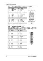
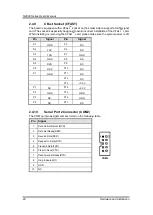
Страница 24: ...TS1 20 MDTR1 21 MTXD1 22 COM1GND 23 COM1GND 24 MRXD1 25 NDSR1 26 NCTS1 2 4 5 ATX Power Connector CN1 Steady and sufficient power can be supplied to all components on the board by connecting the power connector Please make sure all components and devices are properly installed before connecting the power connector Pin Signal Pin Signal CN1 1 3 3V 2 3 3V 3 GND 4 5V 5 GND 6 5V 7 GND 8 PWR_OK 9 5VSB 1...

Страница 25: ...orts They are computer bus interfaces for connecting to devices such as serial ATA hard disk drives Each SATA connector supports a single SATA device Pin Signal Pin Signal SATA1 SATA2 SATA3 SATA4 1 GND 2 TX 3 TX 4 GND 5 RX 6 RX 7 GND 2 4 8 USB Port Connectors USB2 The 10 pin standard Universal Serial Bus USB connector on this board is for installing versatile USB interface peripherals Pin Signal P...

Страница 26: ... sure the system power is off 2 4 10 Serial Port 2 Connector COM2 The COM port pin assignments are listed on the following table Pin Signal COM2 1 Data Carrier Detect DCD 2 Data Set Ready DSR 3 Receive Date RXD 4 Request to Send RTS 5 Transmit Data TXD 6 Clear to Send CTS 7 Data Terminal Ready DTR 8 Ring Indicator RI 9 GND 10 NC Pin Signal Pin Signal S1 GND P5 NC S2 TXP P6 NC S3 TXN P7 GND S4 GND ...

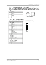
Страница 27: ...de power to these system fans default use FAN2 and FAN3 for system Pin Signal FAN1 FAN2 FAN3 1 Ground 2 12V 3 Rotation Detection 2 4 12 VGA Connector VGA1 This is a 16 pin connector which is commonly used for CRT VGA monitor 1 2 VGA1 Pin Signal 1 VGA_R 2 CRT_DETECT 3 VGA_G 4 NC 5 VGA_B 6 GND 7 VCC 5V 8 VGADDCDATA 9 GND 10 GND 11 GND 12 DAC_L_HSYNC 13 GND 14 DAC_L_VSYNC 15 VGADDCCLK 16 NC ...

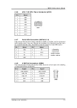
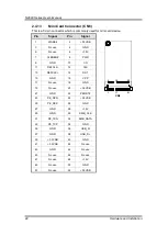
Страница 28: ...se 4 GND 5 No use 6 1 5V 7 CLKREQ 8 PWR 9 GND 10 I O 11 REFCLK 12 CLK 13 REFCLK 14 RST 15 GND 16 VPP 17 No use 18 GND 19 No use 20 3 3VSB 21 GND 22 PERST 23 PE_RXN 24 3 3VSB 25 PE_RXP 26 GND 27 GND 28 1 5V 29 GND 30 SMB_CLK 31 PE_TXN 32 SMB_DATA 33 PE_TXP 34 GND 35 GND 36 USB_D 37 GND 38 USB_D 39 3 3VSB 40 GND 41 3 3VSB 42 No use 43 GND 44 No use 45 No use 46 No use 47 No use 48 1 5V 49 No use 50 ...

Страница 29: ...4 GND 5 No use 6 1 5V 7 CLKREQ 8 PWR 9 GND 10 I O 11 REFCLK 12 CLK 13 REFCLK 14 RST 15 GND 16 VPP 17 No use 18 GND 19 No use 20 3 3VSB 21 GND 22 PERST 23 SATA0_RXP 24 3 3VSB 25 SATA0_RXN 26 GND 27 GND 28 1 5V 29 GND 30 SMB_CLK 31 SATA0_TXN 32 SMB_DATA 33 SATA0_TXP 34 GND 35 GND 36 USB_D 37 GND 38 USB_D 39 3 3VSB 40 GND 41 3 3VSB 42 No use 43 GND 44 No use 45 No use 46 No use 47 No use 48 1 5V 49 N...

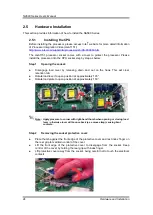
Страница 30: ...er by releasing down and out on the hook This will clear retention tab Rotate load lever to open position at approximately 135 Rotate load plate to open position at approximately 150 Note Apply pressure to corner with right hand thumb when opening or closing load lever otherwise lever will bounce back as a mouse trap causing bent contacts Step 2 Removing the socket protective cover Place thumb aga...

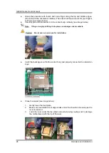
Страница 31: ...uring installation Step 3 Processor installation Lift processor package from shipping media by grasping the substrate edges Scan the processor package gold pads for any presence of foreign material If necessary the gold pads can be wiped clean with a soft lint free cloth and isopropyl alcohol Locate connection 1 indicator on the processor which aligns with connection 1 indicator chamfer on the soc...

Страница 32: ... see image below Note Tilting or roughly shifting it into place can damage socket contacts Caution Do not use a vacuum pen for installation Verify that package is within the socket body and properly connected to orientation keys Close the socket see image below 1 Gently lower the load plate 2 Make sure load plate s front edge slides under the shoulder screw cap as the lever is lowered 3 Latch the ...

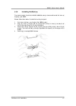
Страница 33: ...install the memory modules 1 Push down latches on each side of the DIMM socket 2 Align the memory module with the socket that notches of memory module must match the socket keys for a correct installation 3 Install the memory module into the socket and push it firmly down until it is fully seated The socket latches are levered upwards and clipped on to the edges of the DIMM 4 Install any remaining...

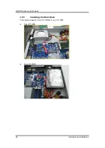
Страница 34: ...NA580 Series User s Manual 28 Hardware and Installation 2 5 3 Installing the Hard Disks The system supports or two 2 5 HDDs or one 3 5 HDD Two 2 5 HDD One 3 5 HDD ...

Страница 35: ...ility uses a key based navigation system called hot keys Most of the BIOS setup utility hot keys can be used at any time during the setup navigation process These keys include F1 F2 Enter ESC Arrow keys and so on Note Some of the navigation keys differ from one screen to another Hot Keys Description Left Right The Left and Right Arrow keys allow you to select a setup screen Up Down The Up and Down...

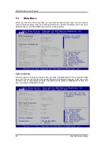
Страница 36: ... Main tab System Time Date can be set up as described below The Main BIOS setup screen is shown below System Date Time Use this option to change the system time and date Highlight System Time or System Date using the Arrow keys Enter new values through the keyboard Press the Tab key or the Arrow keys to move between fields The date must be entered in MM DD YY format The time is entered in HH MM SS...

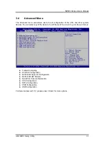
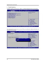
Страница 37: ...stem devices You can select any of the items in the left frame of the screen to go to the sub menus Trusted Computing PCH FW Configuration NCT6102D Super IO Configuration NCT6102D HW Monitor Serial Port Console Redirection CPU Configuration SATA Configuration CSM Configuration USB Configuration For items marked with please press Enter for more options ...

Страница 38: ... Setup Utility Trusted Computing This item supports security devices Enable or Disable BIOS support for security devices If you installed the Security device such as TPM you could see the following information for the TPM device and status ...

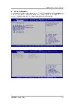
Страница 39: ...Configuration You can use this screen to select options for the PCH FW Configuration and change the value of the selected option A description of the selected item appears on the right side of the screen For items marked with please press Enter for more options ...

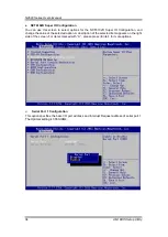
Страница 40: ... IO Configuration and change the value of the selected option A description of the selected item appears on the right side of the screen For items marked with please press Enter for more options Serial Port 1 Configuration This option specifies the base I O port address and Interrupt Request address of serial port 1 The Optimal setting is 3F8h IRQ4 ...

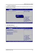
Страница 41: ...S Setup Utility 35 Serial Port 2 Configuration This option specifies the base I O port address and Interrupt Request address of serial port 2 The Optimal setting is 2F8h IRQ3 NCT6102D H W Monitor This screen monitors is hardware health ...

Страница 42: ...speed in RPM and system voltages VCORE 1 5V and 12V Serial Port Console Redirection Console Redirection Use this item to enable or disable console redirection The settings specify how the host computer and remote computer which the user is using will exchange data Both computers should have the same or compatible setting ...

Страница 43: ...NA580 Series User s Manual AMI BIOS Setup Utility 37 Console Redirection Settings ...

Страница 44: ...t the data bits The configuration options 1 and 2 Flow Control This item allows you to select flow control for console redirection The configuration options None and Hardware RTS CTS VT UTF8 Combo Key Support Use this item to Enabled and Disabled VT UTF8 combination key supports for ANSI VT100 terminals Recorder Mode This item allows you to select the recorder mode The configuration options Enable...

Страница 45: ...S POST Use this item to enable or disable the function of Console Redirection which allows you maintain a system from a remote location The default setting is Always CPU Configuration This screen shows the CPU Configuration and you can change the value of the selected option ...

Страница 46: ...tions for the SATA Configuration and change the value of the selected option A description of the selected item appears on the right side of the screen In this menu you can see the currently installed hardware in the SATA ports During system boot up the BIOS automatically detects the presence of SATA devices ...

Страница 47: ...tem to choose the SATA operation mode Here are the options for your selection IDE Mode or AHCI Mode or RAID Mode RAID function only for NA580 which is C236 PCH CSM Configuration This screen shows the CSM Configuration and you can enable disable option ROM execution settings ...

Страница 48: ...On All SEG For Power On LAN Bypass setting use LBP PowerOn item to Disabled Enabled or Last State for LAN Bypass all segments LBP Power Off All SEG For Power off LAN Bypass setting use LBP PowerOff item to Disabled Enabled or Last State for LAN Bypass all segments ...

Страница 49: ...A580 Series User s Manual AMI BIOS Setup Utility 43 Network For Network setting use Network item to Do not launch or legacy mode USB Configuration Use this item for further setting USB port configuration ...

Страница 50: ...on This should be enabled for complete USB keyboard legacy support for non USB OS USB transfer time out Setting 20seconds time out interval the host controller starts a timer when it receives the transfer request Device reset time out This option sets the reset timing for the USB Mass Storage to be initialized When set to 10 Sec the BIOS will wait for up to 40 seconds for the USB flash drive to in...

Страница 51: ...nu The Chipset menu allows users to change the advanced chipset settings You can select any of the items in the left frame of the screen to go to the sub menus System Agent SA Configuration PCH IO Configuration For items marked with please press Enter for more options ...

Страница 52: ...NA580 Series User s Manual 46 AMI BIOS Setup Utility System Agent SA Configuration Memory Configuration This screen allows users to configure parameters of North Bridge Chipset ...

Страница 53: ...NA580 Series User s Manual AMI BIOS Setup Utility 47 PCH IO Configuration ...

Страница 54: ...the system Administrator Password This item indicates whether an administrator password has been set If the password has been installed Installed displays If not Not Installed displays User Password This item indicates whether an user password has been set If the password has been installed Installed displays If not Not Installed displays ...

Страница 55: ...to change boot options of the system Setup Prompt Timeout Number of seconds to wait for setup activation key 65535 0xFFFF means indefinite waiting Boot Option Priorities You could set the system boot order of the legacy devices in this group You could sets the system boot order in option 1 or 2 ...

Страница 56: ...ad your system configuration with optimal or fail safe default values Save Changes and Exit When you have completed the system configuration changes select this option to leave Setup and return to Main Menu Select Save Changes and Exit from the Save Exit menu and press Enter Select Yes to save changes and exit ...

Страница 57: ... Discard Changes and Exit from the Save Exit menu and press Enter Select Yes to discard changes and exit Save Changes and Reset When you have completed the system configuration changes select this option to leave Setup and reboot the computer so the new system configuration parameters can take effect Select Save Changes and Reset from the Save Exit menu and press Enter Select Yes to save changes a...

Страница 58: ...the system configuration and reboot the computer Select Discard Changes and Reset from the Save Exit menu and press Enter Select Yes to discard changes and reset Save Changes When you have completed the system configuration changes select this option to save changes Select Save Changes from the Save Exit menu and press Enter Select Yes to save changes ...

Страница 59: ...es to discard changes Restore Defaults It automatically sets all Setup options to a complete set of default settings when you select this option The Optimal settings are designed for maximum system performance but may not work best for all computer applications In particular do not use the Optimal Setup options if your computer is experiencing system configuration problems Select Restore Defaults ...

Страница 60: ...onfiguration changes done so far as User Defaults Select Save as User Defaults from the Save Exit menu and press Enter Restore User Defaults It automatically sets all Setup options to a complete set of User Defaults when you select this option Select Restore User Defaults from the Save Exit menu and press Enter ...

Страница 61: ...g into the OS If you don t do any change the state will keep the previous power off state The NA580 has LAN bypass capability with the special designed latch relay circuitry When LAN bypass function is enabled a relay closes to act as a bridge to route network data flow between LAN module s LAN port 0 and LAN port 1 or LAN port 2 and LAN port 3 etc Motherboard has 2 pairs of latch type LAN bypass ...

Страница 62: ...8E0 0x8E4 7 6 5 4 3 2 1 0 BYM1 BYM0 X X SEGN4 SEGN3 SEGN2 SEGN1 W W W W W W Default value 00000000 Bit 7 6 BYM1 0 These bits are used to set bypass mode 00 Not used 01 Force bypass enable Relay closes immediately to form LAN bypass on selected segment when power on 10 Force bypass disable LAN bypass is disabled immediately on selected segment when power on ...

Страница 63: ... status will be kept on power off bypass state Power OFF Bypass Control Register Address Mother board LAN module 0x8E1 0x8E5 7 6 5 4 3 2 1 0 X X X X SEGF4 SEGF3 SEGF2 SEGF1 W W W W Default value 00000000 Bit 7 4 Not used Bits3 0 SEGF4 1 Use the corresponding bit to configure each segment Setting the bit to 1 enables LAN bypass on the segment when power off Clearing the bit to 0 disables LAN bypass...

Страница 64: ...en value Software must write count value periodically to ensure that timer will never expire If timer timeout occurs relay s automatically close to form LAN bypass on selected segment s based on the setting of Power On Bypass Control register SEGN4 SEGN1 Data bits 6 0 read back from this register is not defined and therefore must be ignored A read operation upon this register should not refresh th...

Страница 65: ...ystem Reset WDT Watchdog Timer The hardware supports the WDT Watchdog Timer function While time out happens after a defaulted period the WDT will reset the system Note The sample codes for the above features can be found in the CD and they are only for customers reference as remarked ...

Страница 66: ...NA580 Series User s Manual 60 WDT Timer for System Rese This page is intentionally left blank ...

Страница 67: ... 4 Intel i210AT 2 v AX93336 4GIL 4 Intel i350 2 v GbE Fiber Modules AX93322 8FI 8 Intel 82580EB 0 v AX93322 8MIL 4 4 Intel 82580EB 2 v AX93336 4FI 4 Intel i350 0 v 10GbE Copper Modules AX93317 2GIL 2 Intel X540 1 v 10GbE Fiber Modules AX93307 2FI 2 Intel 82599ES 0 v AX93307 2FIL 2 Intel 82599ES 1 v AX93327 4FI 4 Intel XL710 0 v LAN Bypass Control Jumper JP2 JP3 Use this jumper to select the LAN By...

Страница 68: ... port 2 port 3 port 4 port 5 port 6 port 7 port 8 The orange LED is on when the LAN port connection is working The LED flashes when transmitting or receiving any signals to or from the appliance The LED is dark when the appliance is off Link LED for LAN port 1 port 2 port 3 port 4 port 5 and port 6 port 7 port 8 The double color LED light indicates 10 100 1000Mbps transfer rate When the orange col...

Страница 69: ...e The LED is dark when the appliance is off Link LED for LAN port 1 port 2 port 3 port 4 The double color LED light indicates 10 100 1000Mbps transfer rate When the orange color LED light is radiating it should be 1000Mbps transfer rate When the green color LED light is radiating it should be 100Mbps transfer rate If the Link LED is dark and Active LED is light on or flashing it should be 10Mbps t...

Страница 70: ...NA580 Series User s Manual 64 LAN Module Expansion AX93336 4FI Transfer Rate LED Light Color Fiber port Active Orange Fiber port Link Orange ...

Страница 71: ...A580 Series User s Manual LAN Module Expansion 65 AX93322 8FI Transfer Rate LED Light Color Down Fiber port Active Orange Up Fiber port Active Orange Down Fiber port Link Orange Up Fiber port Link Orange ...

Страница 72: ...rt 3 port 4 The orange LED is on when the LAN port connection is working The LED flashes when transmitting or receiving any signals to or from the appliance The LED is dark when the appliance is off Link LED for LAN port 1 port 2 port 3 port 4 The double color LED light indicates 10 100 1000Mbps transfer rate When the orange color LED light is radiating it should be 1000Mbps transfer rate When the...

Страница 73: ...is on when the LAN port connection is working The LED flashes when transmitting or receiving any signals to or from the appliance The LED is dark when the appliance is off Link LED for LAN port 1 port 2 The double color LED light indicates 1000 10000Mbps transfer rate When the orange color LED light is radiating it should be 10000Mbps transfer rate When the green color LED light is radiating it sh...

Страница 74: ...g or receiving any signals to or from the appliance The LED is dark when the appliance is off Link LED for LAN port 1 port 2 The double color LED light indicates 1000 10000Mbps transfer rate When the orange color LED light is radiating it should be 10000Mbps transfer rate When the green color LED light is radiating it should be 1000Mbps transfer rate When this LED and Link Active LED both are dark...

Страница 75: ...8A maximum Minimum clearance from uninsulated live parts 4 0 mm The equipment is to be installed in an environment with maximum ambient temperature must not exceed 40 C The openings on the enclosure are for air convection hence protected the equipment from overheating DO NOT COVER THE OPENINGS Lay this equipment on a reliable surface when install A drop or fall could cause injury The equipment sha...

Страница 76: ...NA580 Series User s Manual 70 Warning This page is intentionally left blank ...

Отзывы: