MVS900-511/512-FL
Operating
46
4.2 Application
This section shows the real cases in the machine vision field.
4.2.1
Scenario 1
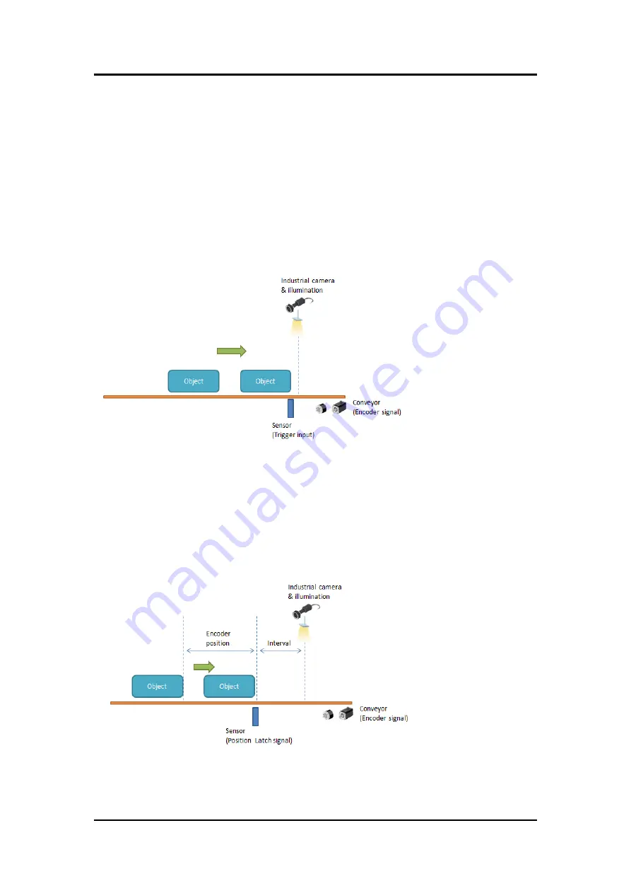
In this scenario, when an optical sensor or encoder detects objects passing down the
production line, it will send trigger signals to notify the system. These signals trigger a camera
to capture images. Data from the camera is then used by a vision platform to identify features.
Finally, should an object with defects be detected, it is rejected by a pneumatic actuator or
robotic arm. These functions will provide real-time I/O with microsecond-scale control and
lighting control to meet timing sequence requirements and ensure high quality image output.
4.2.2
Scenario 2
In this application, the system needs to record the encoder positions for camera trigger. The
AX92352’s hardware is specifically designed to store encoder positions. When the sensor
produces an external latch input signal, the encoder position value will be recorded to the latch
register. Users can get these position data by calling API and set value to the FIFO buffer.
Further, trigger-out will output the FIFO data, which adds up both latch and interval values.
Содержание MVS900-511-FL Series
Страница 1: ...MVS900 511 FL series MVS900 512 FL series Fanless Vision System User s Manual...
Страница 6: ...vi A 2 How to Use Watchdog Timer 71 A 3 Sample Program 72...
Страница 28: ...MVS900 511 512 FL 22 Introduction This page is intentionally left blank...
Страница 46: ...MVS900 511 512 FL 40 I O Connection This page is intentionally left blank...
Страница 57: ...MVS900 511 512 FL AMI BIOS Utility 51 Hardware Monitor This screen monitors hardware health...
Страница 62: ...MVS900 511 512 FL AMI BIOS Utility 56 PCH FW Configuration Display ME firmware information...
Страница 68: ...MVS900 511 512 FL AMI BIOS Utility 62 Memory Configuration This screen shows Memory information...


![Lenovo 90B6 [H50-50 ES] User Manual preview](http://thumbs.mh-extra.com/thumbs/lenovo/90b6-h50-50-es/90b6-h50-50-es_user-manual_201023-01.webp)


