MANO831 Mini ITX Board
Board and Pin Assignments
9
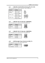
2.2.3
COM4 RS-232/422/485 Mode Setting (JP4, JP5, JP6)
This jumper allows you to select the operation mode of COM port 4.
2.2.4
COM3 RI/+5V/+12V Selection (JCOMPWR3)
This jumper allows you to select the power mode of COM port 3.
2.2.5
COM4 RI/+5V/+12V Selection (JCOMPWR4)
This jumper allows you to select the power mode of COM port 4.
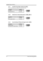
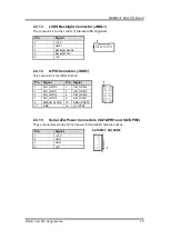
2.2.6
LVDS Backlight Power Selection (JLVDS_P1)
This jumper allows you to select LVDS backlight power.
Function
Setting
RS-232 mode
(Default)
JP4 1-3, 2-4 close
JP5 1-2 close
JP6 1-3, 2-4 close
RS-422 mode
JP4 3-5, 4-6 close
JP5 3-4 close
JP6 3-5, 4-6 close
RS-485 mode
JP4 3-5, 4-6 close
JP5 5-6 close
JP6 3-5, 4-6 close
Function
Setting
+12V
1-2 close
RI (Default)
3-4 close
+5V
5-6 close
Function
Setting
+12V
1-2 close
RI (Default)
3-4 close
+5V
5-6 close
Function
Setting
+5V
1-2 close
+3.3V (Default)
2-3 close
Содержание Mano831 Series
Страница 1: ...MANO831 Series Intel AtomTM D2550 Mini ITX Motherboard User s Manual ...
Страница 10: ...MANO831 Mini ITX Board 4 Introduction 1 4 Block Diagram ...
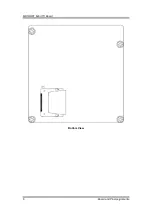
Страница 12: ...MANO831 Mini ITX Board 6 Board and Pin Assignments Bottom View ...
Страница 26: ...MANO831 Mini ITX Board 20 Board and Pin Assignments This page is intentionally left blank ...
Страница 36: ...MANO831 Mini ITX Board 30 Hardware Installation This page is intentionally left blank ...
Страница 39: ...MANO831 Mini ITX Board Hardware Description 33 ...
Страница 41: ...MANO831 Mini ITX Board Hardware Description 35 ...
Страница 42: ...MANO831 Mini ITX Board 36 Hardware Description ...
Страница 43: ...MANO831 Mini ITX Board Hardware Description 37 4 6 Memory Map The memory mapping list is shown as follows ...
Страница 44: ...MANO831 Mini ITX Board 38 Hardware Description This page is intentionally left blank ...

