background image

GOT3177T-834-FR 

User’s Manual


Introduction


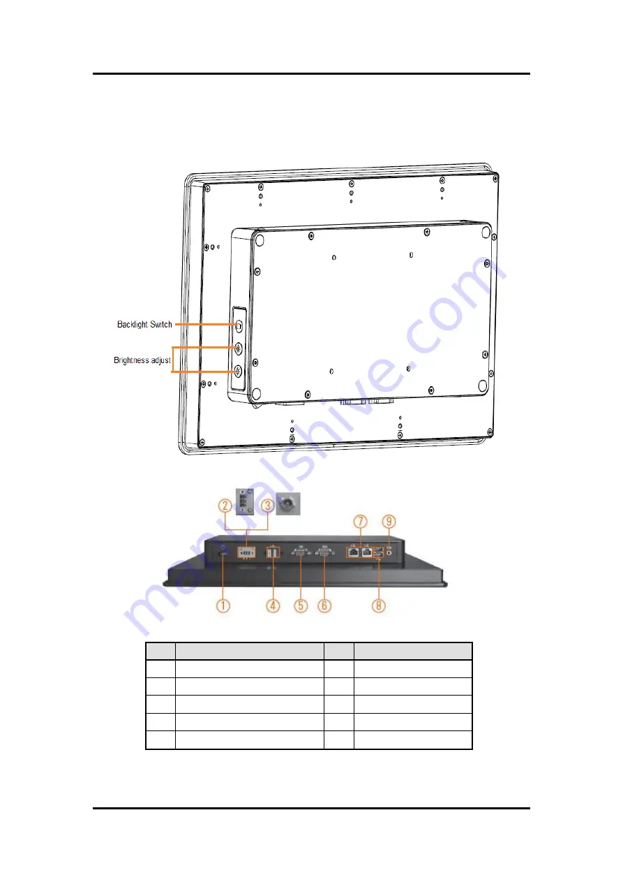
1.4  I/O Outlets 

 
Please refer to the following illustration for I/O locations of the GOT3177T-834-FR. 


No 

Function 

No 

Function 

POWER SWITCH (ATX) 

COM2 (RS-232/422/485) 

Power Input connector (Phoenix) 

Ethernet 

Power Input connector (Screw) 

USB 3.0 

USB 2.0 

  Line-out (Audio) 

COM1 (RS-232/422/485) 


Содержание GOT3177T-834

Страница 1: ...GOT3177T 834 FR All in One 17 SXGA TFT Fanless Compact Size PANEL PC User s Manual ...

Страница 2: ... manual Axiomtek reserves the right to change or revise this document and or product at any time without notice No part of this document may be reproduced stored in a retrieval system or transmitted in any form or by any means electronic mechanical photocopying recording or otherwise without the prior written permission of Axiomtek Co Ltd CAUTION If you replace wrong batteries it causes the danger...

Страница 3: ...ly a trained technician is allowed to do so Integrated circuits on computer boards are sensitive to static electricity To avoid damaging chips from electrostatic discharge observe the following precautions Before handling a board or integrated circuit touch an unpainted portion of the system unit chassis for a few seconds This will help to discharge any static electricity on your body When handlin...

Страница 4: ...Switch Setting 12 2 3 1 Auto Power On JP7 13 2 3 2 Restore BIOS Optimal Defaults JP8 13 2 3 3 COM port Connector 13 2 4 Ethernet 14 2 5 Mountings Panel Wall Desktop VESA 15 2 5 1 VESA ARM Wall Mount 15 2 5 2 Panel mount Kit Assembly 16 2 6 HDD Installation 17 2 7 DRAM Installation 19 2 8 Wireless LAN Card Installation 21 2 9 Power Input 23 Chapter 3 AMI BIOS Setup Utility 25 3 1 Navigation Keys 25...

Страница 5: ...apter 4 Drivers Installation 43 4 1 System 43 4 1 1 Win 7 43 4 1 2 Win 8 8 x 44 4 2 Touch Screen 44 4 2 1 Specification 44 4 2 2 Driver Installation Windows 7 8 x 45 4 3 Embedded O S 47 4 3 1 WES 7 WE8S 47 ...

Страница 6: ...vi This page is intentionally left blank ...

Страница 7: ...ems and many more Having below abilities makes GOT3177T 834 FR surely a most robust and cost effective solution Wide Operating Temperature Range GOT3177T 834 FR features a technology of wide operating temperature range which allows it to work between 10 C to 50 C It incorporates compact ID and fanless cooling system with a low power Intel Celeron Processor J1900 2M Cache up to 2 42 GHz making the ...

Страница 8: ...O including RS 232 422 485 USB 2 0 USB 3 0 audio line out and Gigabit Ethernet Additionally this slim unit supports panel mount wall mount optional VESA mount optional and desktop stand optional 1 2 Specifications Main CPU Board CPU Intel Celeron Processor J1900 2M Cache up to 2 42 GHz onboard System Memory One 204 pin DDR3L SO DIMM socket Maximum memory up to 8GB BIOS America Megatrends BIOS I O ...

Страница 9: ...ration Temperature 10 to 50 Relative Humidity 20 to 90 40 Non Condensing System Power input DC power input 9 36VDC with phoenix power connector AC power input 12VDC 60W power adapter NOTE All specifications and images are subject to change without notice If the operation temperature is higher than 40 the wide temperature HDD CFast TM are recommended to be used on the device If the operation temper...

Страница 10: ...GOT3177T 834 FR User s Manual 4 Introduction 1 3 Dimensions and Outlines The following diagrams show the dimensions and outlines of GOT3177T 834 FR ...

Страница 11: ...GOT3177T 834 FR User s Manual Introduction 5 ...

Страница 12: ...fer to the following illustration for I O locations of the GOT3177T 834 FR No Function No Function 1 POWER SWITCH ATX 6 COM2 RS 232 422 485 2 Power Input connector Phoenix 7 Ethernet 3 Power Input connector Screw 8 USB 3 0 4 USB 2 0 9 Line out Audio 5 COM1 RS 232 422 485 ...

Страница 13: ...the GOT3177T 834 FR the bundled package should contain the following items GOT3177T 834 FR unit x 1 Driver CD x1 Phoenix connector x 1 Panel mount kit x 10 Screws for HDD x 4 If you can not find the package or any items are missing please contact Axiomtek distributors immediately ...

Страница 14: ...GOT3177T 834 FR User s Manual 8 Introduction This page is intentionally left blank ...

Страница 15: ...3177T 834 FR provides rich I O ports and flexible expansions for you to meet different demand for example CF card The chapter will show you how to install the hardware It includes CFast Card Open Back Cover Jumper and Switch Setting Ethernet Mounting Method Hard disk DRAM Wireless LAN Card Power Input ...

Страница 16: ...stTM card Installation The GOT3177T 834 FR provides one CFast slot for users to install CFast card Please refer to the following instructions for installation Step 1 Open the cover unscrew 2 screws on the chassis Step 2 Stick the mylar on the CFast TM card bottom side ...

Страница 17: ... CFast TM card to the CFast TM card slot then finding the CFast TM cover from the system package and screw it 2 2 Open back cover This section tells users how to open back cover Please follow the steps below Step 1 Unscrew 8 screws on the back cover Please refer the photo below ...

Страница 18: ...s to open The following illustration shows how to set up jumper Before applying power to GOT3177T 834 FR please make sure all of the jumpers and switch are in factory default position Below you can find a summary table and onboard default settings Jumper Description Setting JP7 Auto Power On Default Disable 2 3 close JP8 Restore BIOS Optimal Defaults Clear CMOS Default Normal Operation 1 2 close J...

Страница 19: ...n 2 3 for a few seconds then move it back to pin 1 2 Doing this procedure can restore BIOS optimal defaults 2 3 3 COM port Connector The pin assignment of RS 232 RS 422 RS 485 is listed on the following table Function Setting Enable auto power on 1 2 close Disable auto power on Default 2 3 close Function Setting Normal operation Default 1 2 close Restore BIOS optimal defaults 2 3 close Pin RS 232 ...

Страница 20: ...l compliant with IEEE 802 3 standard and can be connected with a RJ 45 LAN connector Please refer to detailed pin assignment list below Pin Signal 1 2 3 4 5 6 7 8 RJ 45 1 TX Data transmission positive 2 TX Data transmission negative 3 Rx Data reception positive 4 RJ45 termination 5 RJ45 termination 6 Rx Data reception negative 7 RJ45 termination 8 RJ45 termination ...

Страница 21: ...ings Panel Wall Desktop VESA There are 4 application options for the GOT3177T 834 FR Panel Wall Desktop VESA mountings 2 5 1 VESA ARM Wall Mount The GOT3177T 834 FR provides VESA mount 100x100 mm Screw four screws to fix the kit in the back chassis Wall mount VESA mount ...

Страница 22: ...ual 16 Hardware and Installation 2 5 2 Panel mount Kit Assembly The GOT3177T 834 FR is designed for panel mount application To mount the GOT3177T 834 FR the standard set of mounting kit included in the system packaging is needed ...

Страница 23: ...ation 17 2 6 HDD Installation The GOT3177T 834 FR provides a convenient Hard Disk Drive HDD bracket for users to install 2 5 SATA HDD Please follow the steps Step 1 Refer section 2 2 to open the back cover Step 2 Fix the HDD on the HDD tray by 4 screws ...

Страница 24: ...GOT3177T 834 FR User s Manual 18 Hardware and Installation Step 3 Plug the cables to connectors and screw the HDD tray on the bracket Installation completes ...

Страница 25: ...n DDR3L SODIMM socket that supports system memory up to 8GB Please follow steps below to install the memory modules Step 1 Refer to section 2 2 to open the back cover Step 2 Find the DIMM heatsink on the back cover Stick the thermal pad on it and rip the red mylar from it Step 3 Find out DIMM socket on mainboard SBC87834 ...

Страница 26: ...GOT3177T 834 FR User s Manual 20 Hardware and Installation Step 4 Insert the DRAM to the DIMM socket and then push it down firmly until it is clipped by the socket Installation completed ...

Страница 27: ...card slot for user to install one wireless LAN card When installing the wireless LAN card refer to the following instructions and illustration Step 1 Refer to section 2 2 to open the back cover and find out mini card slot on mainboard Step 2 Insert the wireless LAN card to the slot Push it down firmly until it is clipped by the slot ...

Страница 28: ...GOT3177T 834 FR User s Manual 22 Hardware and Installation Step 3 Find the Antenna cable and connect it on wireless LAN card ...

Страница 29: ...tor NOTE Please have the extended bracket when using half size mini card 2 9 Power Input GOT3177T 834 FR equips with a phoenix type power connector It adopts 9VDC to 36VDC Please follow the signs on power connector to connect DC power source Power positive G Safety ground Power negative NOTE The safety ground must be connected to ensure the unit working appropriately ...

Страница 30: ...GOT3177T 834 FR User s Manual 24 Hardware and Installation This page is intentionally left blank ...

Страница 31: ...Down The Up and Down Arrow keys allow you to select a setup screen or sub screen Plus Minus The Plus and Minus Arrow keys allow you to change the field value of a particular setup item Tab The Tab key allows you to select setup fields F1 The F1 key allows you to display the General Help screen F2 The F2 key allows you to load previous value F3 The F3 key allows you to Load Optimized Defaults F4 Th...

Страница 32: ...Use this option to change the system time and date Highlight System Time or System Date using the Arrow keys Enter new values through the keyboard Press the Tab key or the Arrow keys to move between fields The date must be entered in MM DD YY format The time is entered in HH MM SS format ...

Страница 33: ... frame of the screen to go to the sub menus ACPI Settings NCT6106D Super IO Configuration NCT6106D H W Monitor CPU Configuration IDE Configuration For items marked with please press Enter for more options ACPI Settings You can use this screen to select options for the ACPI Configuration and change the value of the selected option A description of the selected item appears on the right side of the ...

Страница 34: ...l 28 AMI BIOS Setup Utility ACPI Sleep State Allow you to select the Advanced Configuration and Power Interface ACPI state to be used for system suspend Here are the options for your selection Suspend disable and S3 Suspend to RAM ...

Страница 35: ... the selected option Serial Port 1 4 configuration Serial port This option used to enable or disable the serial port Device Setting This item specifies the base I O port address and Interrupt Request address of serial port The port 0 Optimal setting is 3F8 IRQ4 The port 1 Optimal setting is 2F8 IRQ3 The port 2 Optimal setting is 3E8 IRQ7 The port 3 Optimal setting is 2E8 IRQ5 ...

Страница 36: ...GOT3177T 834 FR User s Manual 30 AMI BIOS Setup Utility Serial type This option used to select RS232 422 485 function ...

Страница 37: ...GOT3177T 834 FR User s Manual AMI BIOS Setup Utility 31 NCT6106D H W Monitor This screen shows the Hardware Health Configuration ...

Страница 38: ...GOT3177T 834 FR User s Manual 32 AMI BIOS Setup Utility CPU Configuration This screen shows the CPU Configuration and Intel virtualization technology enable disable selected ...

Страница 39: ...y 33 IDE Configuration You can use this screen to select options for the SATA Configuration and change the value of the selected option SATA Mode Use this item to choose the SATA operation mode Here are the options for your selection IDE Mode AHCI Mode ...

Страница 40: ...GOT3177T 834 FR User s Manual 34 AMI BIOS Setup Utility Intel TXE Configuration The Advanced menu allows users to update the TXE firmware ...

Страница 41: ...CC Configuration You can select any of the items in the frame of the screen to change the OS the default setting is Win 7 Please be informed to select the Windows 8 x when installing Win 8 or Win 8 1 If using the Android OS please refer to https 01 org android ia ...

Страница 42: ...GOT3177T 834 FR User s Manual 36 AMI BIOS Setup Utility 3 4 Chipset Menu The Chipset menu allows users to change the advanced chipset settings ...

Страница 43: ...GOT3177T 834 FR User s Manual AMI BIOS Setup Utility 37 North Bridge This screen shows the North Bridge memory information South Bridge ...

Страница 44: ...R User s Manual 38 AMI BIOS Setup Utility USB Configuration You can use this screen to select options for the USB Configuration If USB3 0 function used XHCI Mode must enable and EHCI must disable XHCI default is Auto ...

Страница 45: ...GOT3177T 834 FR User s Manual AMI BIOS Setup Utility 39 3 5 Security ...

Страница 46: ... Timeout for wait press key to enter Setup Menu Bootup NumLock State Use this item to select the power on state for the NumLock The default setting is on Quiet Boot Use this item to enable or disable the Quite Boot state The default setting is disable Legacy Pxe OPROM Use this item to enable or disable the Preboot Execution Environment The default setting is disable Boot Option Priorities Specifie...

Страница 47: ...GOT3177T 834 FR User s Manual AMI BIOS Setup Utility 41 3 7 Save Exit ...

Страница 48: ...GOT3177T 834 FR User s Manual 42 AMI BIOS Setup Utility This page is intentionally left blank ...

Страница 49: ...and WE8S To facilitate the installation of system driver please carefully read the instructions in this chapter before start installing 4 1 1 Win 7 1 Insert Driver CD and select the Drivers 2 Select all files and follow the installing procedure NOTE Please install Microsoft KB2685811 before TXE installation under Windows 7 then installing the drivers ...

Страница 50: ...OT3177T 834 FR uses the 5 wire analog resistive flat front bezel type There are the specification and driver installation which are listed below 4 2 1 Specification Touch Screen 5 wire Analog Resistive type Touch Screen Controller PenMount 6000 USB Touch Screen Controller IC Communications USB interface Resolution 1024 x 1024 Power Input 5V Power Consumption Active 24 6mA Idle Mode 13 4mA ...

Страница 51: ...rating system Windows 7 8 x To facilitate installation of the touch screen driver you should read the instructions in this chapter carefully before you attempt installation 1 Insert Driver CD and follow the path to select the Drivers Step 7 Touch 2 Follow the installing procedure and press OK 3 Click Start menu and select PenMount Utilities and then a PenMount Control Panel pops out ...

Страница 52: ...Drivers Installation 4 Select the Standard Calibrate tab 5 Calibration To adjust the display with touch panel click Calibration and follow the calibrate point to do calibration there are five points on screen for calibration 6 Press OK ...

Страница 53: ...ATA HDD USB CRT LCD display 10 100 1000 base T Ethernet CFast TM or mSATA Onboard Audio Touch Screen PenMount Touch screen Before you can use and calibrate it here is what you should do 1 Set up Penmount touch device driver by executing C Penmount Windows 2000 XP V5 0 setup exe When the installation is finished an icon PM appears on the Taskbar 2 Calibrate Penmount touch by clicking on the PM icon...

Страница 54: ...GOT3177T 834 FR User s Manual 48 Drivers Installation This page is intentionally left blank ...

Отзывы: