


GOT115-319
User’s Manual
Drivers Installation
39
Chapter 4
Drivers Installation
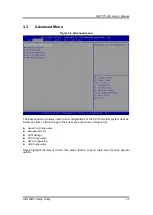
4.1
System
The GOT115-319 supports Windows 10 pro and Windows 10 IoT Enterprise. To facilitate the
installation of the system driver, please carefully read the instructions in this chapter before
installation.
4.1.1 Windows 10
1.
Insert the driver CD and select the folders from step 1 to step 5.
2.
Copy all folders onto the system storage.
3.
Click the setup.exe file in each folder and follow the instructions to complete installation.
4.2
Touch Screen
The GOT115-319 adopts a projected capacitive multi-touch screen or 5-wired analog resistive
touch. The specification is listed in Table 4-1 below. The touch driver will be installed
automatically to enable the touch panel
’s two-finger touch functions based on the Windows 10
and Windows IoT Enterprise support.
Table 4-1 Touch screen specification
Touch Screen
5-wired analog resistive touch
Touch Screen Controller
Penmount 6000 USB touch Screen Controller IC
Communications
USB interface
Resolution
1024 x 1024 resolution
Power Input
5V
Power Consumption
Active: 24.6mA / Idle Mode: 13.4mA
Input Method
Finger or Cap.Stylus
Calibration
Non-Calibration
Содержание GOT115-319
Страница 6: ...vi This page is intentionally left blank ...
Страница 10: ...GOT115 319 User s Manual 4 Introduction 1 3 Dimensions GOT115 319 outlines and dimensions ...
Страница 50: ...GOT115 319 User s Manual 44 Watchdog Timer DIO Programming ...
Страница 51: ...GOT115 319 User s Manual Watchdog Timer DIO Programming 45 ...