UMAX030440 Version 2B 6-51
1
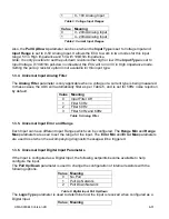
0 - 10V Analog Input
Table 3: Voltage Input Ranges
Value Meaning
0
0 - 20mA Analog Input
1
4 - 20mA Analog Input
Table 4: Current Input Ranges
Also, the
Pull Up/Down
parameter can be set when the
Input Type
is set to Voltage Input and
Input Range
is set to 0-5V Analog Input. It allows the ECU to work in two modes for this input
range: 5V in High Impedance and 5V with 10kOhm Impedance.
Note: It is only possible to set the pull-down resistor either high or low if the Input Type is set to
Input Voltage. If 10kOhm pull-down is disabled, the ECU will run in 5V in High Impedance mode.
Setting the pull-up resistor option is not available for this input type.
1.3.4. Universal Input Analog Filter
The
Analog Filter
parameter is only applicable when a voltage or a current type is being measured.
In these cases, the ADC will automatically filter as per Table 5, and is set for 50Hz noise rejection
by default.
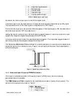
Value Meaning
0
Input Filter Off
1
Filter 50Hz
2
Filter 60Hz
3
Filter 50Hz and 60Hz
Table 5: Analog Filter
1.3.5. Universal Input Error and Range
Each Input can have different Input Ranges which can be configured. The
Range Min
and
Range
Max
parameters are used to set the range for the input. The
Error Min
and
Error Max
parameters
are used to set when the accompanying diagnostic message will be triggered.
1.3.6. Universal Input Digital Input Parameters
If the Input is configured as a Digital Input, the following setpoints become available to help
configure the input.
The
Pull Up/Down
parameter is used to change the configuration of internal resistors with the
following options.
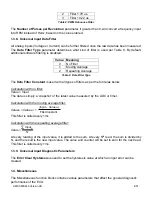
Value Meaning
0
No Pull
1
Pull Up Network
2
Pull Down Network
Table 6: Digital Input Pull Up/Down
The
Logic Type
parameter is used to determine how the input is received when configured as a
Digital Input.
Value Meaning


