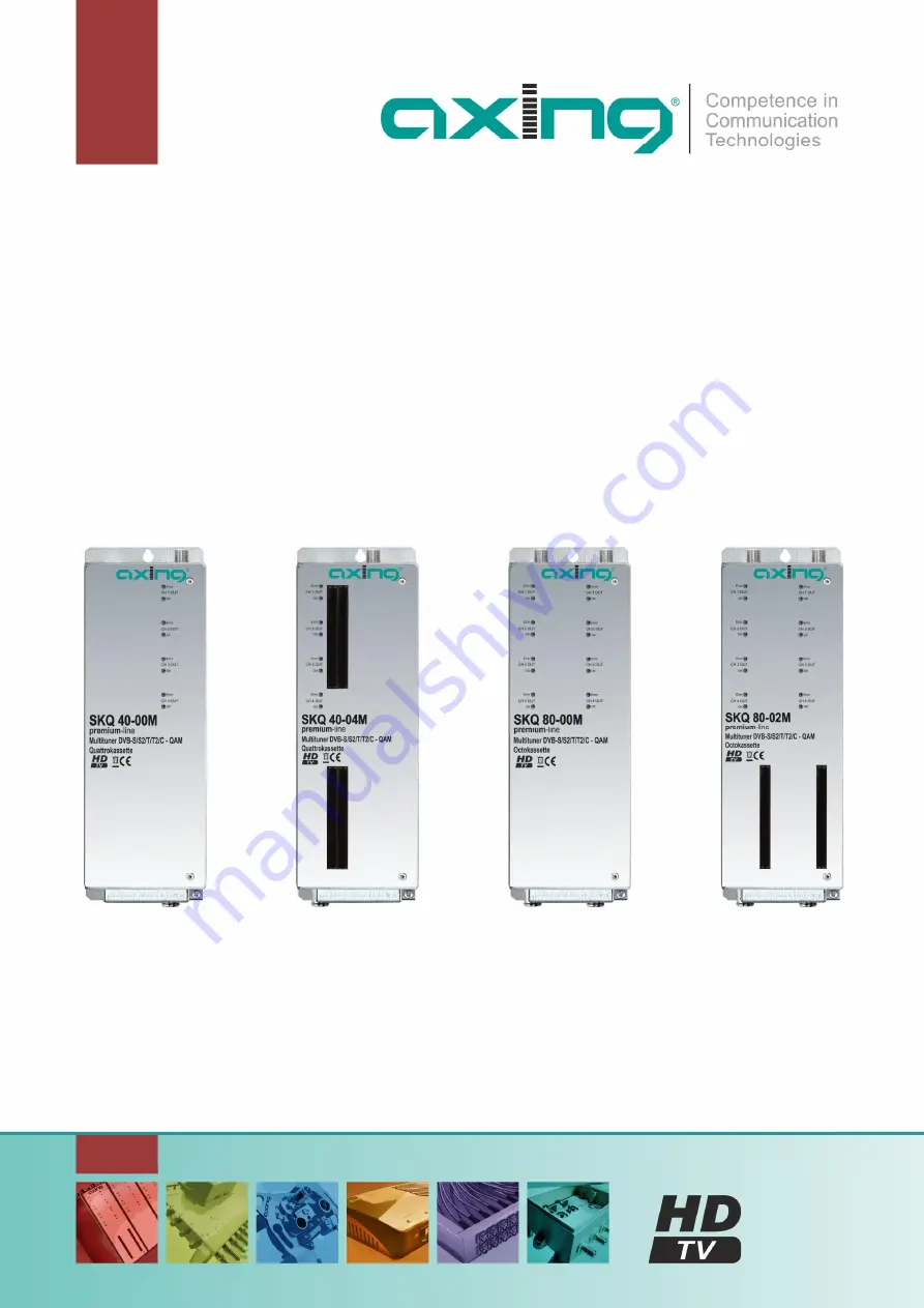
SKQ 40-0x | SKQ 80-0xSKQ 40-0xM | SKQ 80-0xM
8PSK/QPSK bzw. Multituner | QAM-Quattro-/Octokassetten
Betriebsanleitung
Страница 1: ...SKQ 40 0x SKQ 80 0x SKQ 40 0xM SKQ 80 0xM 8PSK QPSK bzw Multituner QAM Quattro Octokassetten Betriebsanleitung ...
Страница 2: ...nfiguration 13 3 1 An und Abmeldung 14 3 2 Startseite 15 3 2 1 Bitfehlerrat und Niveau 15 3 2 2 Füllstand 15 3 2 3 CI Menüs 15 3 2 4 Initialisierung 16 3 3 Initialisierung Phase 1 16 3 3 1 DVB S für 8PSK QPSK und für Multituner Kassetten 16 3 3 2 DVB C DVB T oder DVB T2 für Multituner Kassetten 17 3 3 3 Bitfehlerrate 18 3 3 4 Gefundene Programme 18 3 4 Initialisierung Phase 2 18 3 4 1 Remux Mode 1...
Страница 3: ...7 Technische Änderungen Änderungen im Design Druckfehler und Irrtümer vorbehalten 3 5 Technische Daten 32 5 1 Eingangsdaten Multituner 32 5 2 Eingangsdaten DVB S S2 Tuner 32 5 3 Ausgangsdaten Allgemeine Daten 33 ...
Страница 4: ...efahr oder elektrischen Schlägen Achtung Lebensgefahr Planen Sie den Montage bzw Aufstellort so dass Sie in Gefahrensituationen den Netzstecker leicht erreichen und den Stromkreis unterbrechen können Wählen Sie den Montage bzw Aufstellort so dass Kinder nicht unbeaufsichtigt am Gerät und dessen Anschlüssen spielen können Der Montage bzw Aufstellort muss eine sichere Verlegung aller angeschlossenen...
Страница 5: ...en für CA Module ausgestattet 1 1 2 Kassetten mit Multituner für DVB C DVB T oder DVB T2 SKQ 40 00M Wandelt DVB S S2 T T2 C Cx in QAM Die SKQ 40 00M besitzt vier Multituner vier Modulatoren und einen HF Ausgang SKQ 40 04M Wie SKQ 40 00M zusätzlich mit 4 CI Steckplätzen für CA Module ausgestattet SKQ 80 00M Wandelt DVB S S2 T T2 C Cx in QAM Die SKQ 80 0xM besitzt zwei voneinander getrennte Einheite...
Страница 6: ...über eine Fernspeisespannung für den LNB und über DiSEqC 1 0 Funktionalitäten Die Eingänge können direkt an den LNB angeschlossen werden Multischalter Optional lassen sich auch Multischalter als Eingangsverteiler verwenden Diese Lösung hat den Vorteil dass sowohl die SAT ZF Ebene als auch der Satellit über die Benutzeroberfläche eingestellt werden können Änderungen in der Programmliste können ohne...
Страница 7: ...tor Gruppen mit jeweils vier Modulatoren aufgeteilt Die Octokassette verfügt über zwei HF Ausgänge einer pro Modulatorgruppe In beiden Gruppen kann der erste Modulator auf einen beliebigen Ausgangskanal eingestellt werden Die drei nachfolgenden Modulatoren werden automatisch auf die drei nächsten Kanäle eingestellt Beispiel Gruppe A Modulator 1 Kanal 21 Modulatoren 2 3 und 4 Kanäle 22 23 und 24 Gr...
Страница 8: ...SKQ 40 0xM 1 4 LED Anzeigen MPEG Datenstrom Modulator mit je zwei LEDs Error rot Modulator Stream zu groß Füllstand 95 siehe Abschnitt 3 2 2 auf Seite 15 OK grün Füllstand OK 2 4 HF Eingang 3 RJ 45 Ethernet Anschluss 4 4 HF Eingangs LED Anzeige Orange MPEG Datenstrom vorhanden Aus MPEG Datenstrom nicht vorhanden 5 Potentialausgleichsanschluss 6 1 x HF Ausgang 7 Lüfter 8 2 DC Ein Ausgang 9 4 x CI S...
Страница 9: ...G Datenstrom Modulator mit je zwei LEDs Error rot Modulator Stream zu groß Füllstand 95 OK grün Füllstand OK 2 8 HF Eingang 3 2 RJ 45 Ethernet Anschluss 4 8 HF Eingangs LED Anzeige Orange MPEG Datenstrom vorhanden Aus MPEG Datenstrom nicht vorhanden 5 Potentialausgleichsanschluss 6 2 HF Ausgang 7 Lüfter 8 2 DC Ein Ausgang 9 2 x CI Schacht ...
Страница 10: ...oder Stand Alone mit einem externen Netzteil betrieben werden Montage und Anschluss sind nur von autorisierten Elektrofachkräften durchzuführen Vor Montage und Anschluss Netzteile vom Netz trennen Beachten Sie die Betriebsanleitung der Kopfstellen Grundeinheit Beachten Sie die Betriebsanleitung des Netzteils Die Antennenanlage muss gemäß DIN EN 60728 11 aufgebaut und entsprechend geerdet werden 2 ...
Страница 11: ...eigneten Weichen verbunden werden 2 3 Potentialausgleich Bei der Montage in der Kopfstellen Grundeinheit wird der Potentialausgleich über die Grundeinheit hergestellt Beachten Sie die Betriebsanleitung der Kopfstellen Grundeinheit Bei der Montage als Stand Alone Gerät müssen Sie sowohl die Kassette als auch das Netzteil gemäß EN 60728 11 am Potentialausgleich anschließen Verwenden Sie den am Gerät...
Страница 12: ...nander verbunden werden Beachten Sie den maximalen Ausgangsstrom des verwendeten Netzteils Beachten Sie dass das Netzteil ggf auch die LNBs versorgen muss 2 5 Anschluss an DVB S 2 5 1 Direkter Anschluss an LNBs Die Kopfstellen Kassetten verfügen an den Eingängen über eine Fernspeisespannung für den LNB und über DiSEqC 1 0 Funktionalitäten Die Eingänge können direkt an den LNB angeschlossen werden ...
Страница 13: ...e statische IP Adresse Ab Werk sind folgende Werte voreingestellt Quattrokassette IP Adresse 192 168 0 145 Octokassette IP Adresse linke Seite 192 168 0 145 IP Adresse rechte Seite 192 168 0 146 Subnetzmaske 255 255 255 0 Der Computer und die Kassette müssen sich im gleichen Teilnetz befinden Der Netzanteil der IP Adresse des Computers muss auf 192 168 0 und die Subnetzmaske muss auf 255 255 255 0...
Страница 14: ...h Die hier getroffene Sprachauswahl gilt für die Dauer der Sitzung Um sich abzumelden drücken sie auf die Schaltfläche ABMELDEN in der Kopfzeile der Webseite Im Browser erscheint die Meldung Auf Wiedersehen Hinweise Wird der Browser ohne vorherige Abmeldung geschlossen erfolgt nach ca 2 5 Minuten eine automatische Abmeldung Bleibt das Browserfenster geöffnet erfolgt keine automatische Abmeldung Da...
Страница 15: ...der vier Modulatoren angezeigt 100 Modulator Füllstand entsprechen der maximalen Netto Datenrate des Ausgangskanals Wird der maximale Füllstand überschritten kann es zu Bildstörungen wie z Bsp Mosaikbilder kommen Die Datenrate der Sender kann abhängig vom Bildinhalt und Übertragungsqualität variieren Um den störungsfreien Empfang zu gewährleisten ist unbedingt eine Reserve einzuhalten Wir empfehle...
Страница 16: ...ten unabhängig voneinander und nach dem gleichen Prinzip 3 3 1 DVB S für 8PSK QPSK und für Multituner Kassetten Wählen Sie mit den Schaltflächen Tuner 1 4 einen Tuner aus Nehmen Sie die nachfolgend beschriebenen Einstellungen für alle Tuner durch Im Eingabefeld Frequenz MHz die SAT ZF Frequenz des Transponders eingegeben Die Eingabefelder LOF Low Band MHz und LOF High Band MHz beziehen sich auf di...
Страница 17: ...wichtigen Parameter Kanal Eingabe Kanal Eingabe Kanal Eingabe Kanal Eingabe S 21 306 21 474 41 634 61 794 S 22 314 22 482 42 642 62 802 S 23 322 23 490 43 650 63 810 S 24 330 24 498 44 658 64 818 S 25 338 25 506 45 666 65 826 S 26 346 26 514 46 674 66 834 S 27 354 27 522 47 682 67 842 S 28 362 28 530 48 690 68 850 S 29 370 29 538 49 698 69 858 S 30 378 30 546 50 706 S 31 386 31 554 51 714 S 32 394...
Страница 18: ...r auch wieder aktiviert werden Programme können Sie im Remux Mode oder im Cross Multiplex Mode den Ausgangsmodulatoren zuordnen Wichtig Je mehr Programme Sie einem Modulator zuordnen desto höher wird die Datenrate Klicken Sie nachdem Sie Änderungen durchgeführt haben auf die Schaltfläche ÄNDERUNGEN SPEICHERN Erst dadurch werden die Änderungen gespeichert und tatsächlich übernommen 3 4 1 Remux Mode...
Страница 19: ...ion Entschlüsselung Nein oder mit Hilfe eines integrierten CA Moduls in den Kassetten SKQ 40 04 M oder SKQ 80 02 M entschlüsseln Option Entschlüsselung Ja siehe Abschnitt 4 3 auf Seite 31 3 4 2 Cross Multiplex Mode Der Cross Multiplex Mode dient zum Splitten von Transpondern zum Zusammenführen von Programmen aus mehreren Transpondern in einem gemeinsamen Ausgangskanal Dadurch werden die vorhandene...
Страница 20: ... vorbehalten Zusammenführen von Programmen in gemeinsamen Modulatoren Im Cross Multiplex Mode ist die Zuordnung der Tuner zu den Modulatoren aufgehoben Klicken Sie z B in der Tabelle Tuner 1 und in der Tabelle Tuner 3 auf die Modulator Schaltflächen M1 Die drei Programme werden dem Modulator 1 zugeordnet Dem Modulator 1 zugeordnete Programme ...
Страница 21: ... CA Programmen die in der Kopfstelle entschlüsselt werden verwendet werden Ein aufgeteilter Transponder ist wie zwei einzelne Transponder zu sehen Wenn Sie mehrere Kassetten im CROSS MULTIPLEX MODE verwenden dann dürfen die Netzwerk IDs nicht gleich sein Service ID Änderungen der Service ID sind nur notwendig für STBs mit fest voreingestellten ID Diese STBs werden von einigen Providern verwendet d...
Страница 22: ... im REMUX als auch im Cross Multiplex Mode verwendet werden Das Auswahlfeld REGION ist nur für LCN relevant weil der LCN Standard von Region zu Region verschieden sein kann Unterschiedliche LCN Standards können mit diesem Auswahlfeld eingestellt werden Die den Modulatoren zugeordneten Programme erhalten in der Spalte LCN ein Eingabefeld Geben Sie in die Eingabefelder den gewünschten Programmplatz ...
Страница 23: ...ere Sonderkanalbereich und die UHF Kanäle ebenfalls mit 8MHz Bandbreite schliesen sich lückenlos an D24 an Der UHF Bereich ist um die Kanäle CH70 CH87 erweitert Bei der Nutzung dieses Bereichs sollte aber geprüft werden ob alle Empfangsgeräte die Frequenzen oberhalb 862Mhz unterstützen DVB C Modulation Bei der DVB C Modulation kann zwischen 32QAM 64QAM 128QAM und 256QAM gewählt werden 256QAM ermög...
Страница 24: ...and überschritten kann es zu Bildstörungen wie z Bsp Mosaikbilder kommen Die Error LEDs auf der Frontseite leuchten in diesem Fall rot Die Datenrate eines DVB C Kanals hängt von der gewählten Kanalbandbreite 7 oder 8 MHz der eingestellten Symbolrate und der DVB C Modulation QAM 32 64 128 256 des Modulators ab Wenn die angezeigte Datenrate mehr als 95 beträgt gibt es verschiedene Möglichkeiten dies...
Страница 25: ...ann eine neue Software für die Oberfläche installiert werden Software Updates finden Sie auf www axing com Download Nach einem Update wird die Kassette automatisch neu gestartet Die eingestellten Parameter gehen nach einem Update nicht verloren Firmware Updates können ausschließlich werkseitig vorgenommen werden 3 6 2 IP Adresse ändern Unter dem Menüpunkt WARTUNG SYSTEMOPTIONEN kann die IP Adresse...
Страница 26: ...tartet werden Anschließend öffnet sich die Anmeldeseite und Sie müssen sich mit dem neuen Passwort anmelden 3 6 4 Neustart Durch Betätigen der Schaltfläche NEUSTART wird die Kassette neu gestartet Nach dem Neustart müssen Sie sich erneut anmelden Hinweis Wenn zeitweise kein SAT Empfang möglich ist z B bei Schneefall dann startet die Kassette alle 10 Minutern automatisch neu Dadurch wird sichergest...
Страница 27: ...im Download Ordner Ihres PCs gespeichert Klicken Sie auf PDF DRUCKEN es wird ein PDF erzeugt und als Config pdf im Download Ordner Ihres PCs gespeichert Hinweis Passwort und IP Adresse werden nicht gespeichert 3 6 7 Initialisierungsdaten laden Unter EINSTELLUNGEN DER INITIALISIERUNG AUS DATEI LADEN können Sie die gespeicherte Einstellungen der Initialiserungsphasen 1 bis 3 auf eine Kassette laden ...
Страница 28: ...rungen Änderungen im Design Druckfehler und Irrtümer vorbehalten 3 6 8 Gerätenamen eingeben Unter GERÄTENAME können Sie einen Namen für die Kassette eingeben Geben Sie ins Feld GERÄTENAMEN EINGEBEN einen Namen ein Klicken Sie auf Speichern Der Gerätename wird auf der Anmeldeseite angezeigt ...
Страница 29: ... die CI Steckplätze auf der Frontseite der SKQ 80 02 M können bis zu zwei CA Module CAM1 links CAM 1 rechts gesteckt werden Stecken Sie die CA Module vorsichtig ohne Kraftaufwand und seitenrichtig in den entsprechenden CI Steckplatz Hinweis Jedes CAM ist nur dem dazugehörigen Tuner zugeordnet und hat darauf Zugriff SKQ 40 04 M SKQ 80 02 M CAM 1 Tuner 1 CAM 2 Tuner 2 CAM 3 Tuner 3 CAM 4 Tuner 4 CAM...
Страница 30: ...CI Menüs ist vom CAM Hersteller und der verwendeten Karte abhängig Je nach Hersteller sind verschieden Einstellungen möglich Am wichtigsten sind die Informationen über Gültigkeit und Berechtigungen Beachten Sie die Bedienungsanleitung des Herstellers Das Eingabe und Navigationsfeld darunter dient zur Navigation innerhalb des CI Menüs Verwenden Sie Up und Down um zu einen Auswahlpunkt höher oder ti...
Страница 31: ...chlüsselung Werkseitig ist in der Spalte Entschlüsselung die Option NEIN aktiviert Das Programm wird verschlüsselt an den Modulator übergeben und es muss am Empfangsgerät entschlüsselt werden Wenn in den Kassetten CA Module gesteckt sind dann können die entsprechenden Programme entschlüsselt werden Aktivieren Sie in der Spalte Entschlüsselung die Option JA Das Programm wird entschlüsselt an den Mo...
Страница 32: ...om pro Eingang 250 mA Modulationsverfahren 8PSK QPSK COFDM 32k 8k und 2k QAM 16 32 64 128 256 Symbolrate 1 5 45 MS s Fehlerkorrektur automatisch Transportstrom MPEG 2 ISO IEC 13818 MPEG 4 ISO IEC 14496 Anschlüsse 4 F Buchse 8 F Buchse 5 2 Eingangsdaten DVB S S2 Tuner SKQ 40 0x SKQ 80 0x Kanalzüge 4 8 Tuner 4 DVB S S2 8 DVB S S2 Eingangs Frequenzbereich SAT 950 2150 MHz Eingangspegel 43 84 dBµV 65 ...
Страница 33: ...M Ausgang Ausgangsfrequenzbereich 114 1006 MHz Ausgangskanäle S2 K87 Modulation QAM 32 64 128 256 Übertragungssymbolrate 1 7 5 M Symbol sec Ausgangspegel 85 100 dBµV MER 40 dB Anschlüsse 1 F Stecker Quickfix 2 F Stecker Quickfix Allgemein Datenschnittstelle 1 RJ 45 2 RJ 45 Stromaufnahme 16V 1 5 A 16V 3 A Umgebungstemperaturbereich 10 C 50 C Maße ca 72 mm 218 mm 129 mm ...
Страница 34: ...Betriebsanleitung SKQ 40 0x SKQ 80 0x SKQ 40 0xM SKQ 80 0xM 34 2017 01 27 Technische Änderungen Änderungen im Design Druckfehler und Irrtümer vorbehalten ...
Страница 35: ...SKQ 40 0x SKQ 80 0x SKQ 40 0xM SKQ 80 0xM 8PSK QPSK Multituner DVB C Quattro Octo modules Operation instructions ...
Страница 36: ...ction to DVB T T2 or DVB C 12 3 Configuration 13 3 1 Login and logout 14 3 2 Front page 15 3 2 1 Bit error rate 15 3 2 2 Fill level 15 3 2 3 CI menus 15 3 2 4 Initialization 16 3 3 Initialization phase 1 16 3 3 1 DVB S für 8PSK QPSK und für Multituner Kassetten 16 3 3 2 DVB C DVB T or DVB T2 for multi tuner modules 17 3 3 3 Bit error rate 18 3 3 4 Found programmes 18 3 4 Initialization phase 2 18 ...
Страница 37: ...7 Technical changes design modifications errors and misprints are subject to change without prior notice 3 5 Technical specifications 32 5 1 Input multituner 32 5 2 Input DVB S S2 tuner 32 5 3 Output General 33 ...
Страница 38: ...sk of death Plan the mounting or installation location such that you can easily reach the mains plug and interrupt the electric circuit in dangerous situations Select the mounting or installation location such that children cannot play near the device and its connections without supervision The mounting or installation location must allow a safe installation of all connected cables Power supply ca...
Страница 39: ...ble by using two CA modules 1 1 2 Modules with multituner for DVB S S2 DVB T T2 oder DVB C SKQ 40 00M Transmodulates DVB S S2 T T2 C Cx into QAM Four independent multituner inputs four modulators one output SKQ 40 04M Like SKQ 40 00M decoding of encoded programs possible by using four CA modules SKQ 80 00M Transmodulates DVB S S2 T T2 C Cx into QAM The SKQ 80 00M ist built in two units each with f...
Страница 40: ... Cross Multiplex Mode FTA programmes Free to Air can be filtered from the data flow of several tuners for a common output channel and be bundled again The prepared data flow is passed on to the modulators Multiswitches as input distributors Optionally you can also use multiswitches as input distributors The advantage of this solution is that you can set both the SAT IF level and the satellite via ...
Страница 41: ...ided in two modulator groups of four modulators each The octo module has two RF outputs each for one modulator group In both groups the first modulator can be set to any output channel The next three modulators of both modulator groups are automatically set by incrementing the output channels in accordance with the chosen channel spacing For example group A modulator 1 Channel 21 modulators 2 3 un...
Страница 42: ...ctors 1 6 1 SKQ 40 0x SKQ 40 0xM 1 4 MPEG data stream modulator LED indicators each with two LEDs Error red Modulator stream too large fill level 95 see 3 2 2 on page 15 OK green Fill level O K 2 4 HF input 3 RJ 45 Ethernet port 4 4 HF input LED indicator Orange MPEG data stream present Off MPEG data stream not present 5 Equipotential bonding connection 6 1 x HF output 7 Fan 8 2 DC input output 9 ...
Страница 43: ...eam modulator LED indicators each with two LEDs Error red Modulator stream too large fill level 95 see 3 2 2 on page 15 OK green Fill level O K 2 8 HF input 3 2 RJ 45 Ethernet port 4 8 HF input LED indicator Orange MPEG data stream present Off MPEG data stream not present 5 Equipotential bonding connection 6 2 HF output 7 Fan 8 2 DC input output 9 2 x CI slots ...
Страница 44: ... the external power supply unit Installation must be performed by authorized and skilled electricians only Before inserting or changing a module pull the mains plug of the headend base unit from the socket Observe the operation instructions of the corresponding headend base unit Observe the operation instructions of the corresponding power supply unit The antenna system must be installed and groun...
Страница 45: ...puts of several modules must be combined with a distributor 2 3 Equipotential bonding If the device is mounted in the headend base unit the connection to the equipotential bonding has to be done via the headend base unit Observe the operation instructions of the headend base unit If the module is mounted external a headend base unit the module and the power supply unit must be connected to the equ...
Страница 46: ...pply unit with sufficient output power for your application Note that the power supply unit has to supply also the LNBs and the active combiner of the headend base units if necessary 2 5 Connection to DVB S 2 5 1 Connection to the LNBs On the SAT IF input the headend modules have a remote supply voltage for the LNB and use DiSEqC 1 0 functionalities Therefore they can be connected directly to the ...
Страница 47: ... web interface and its own static IP address The following values are preset ex factory Quattro module IP address 192 168 0 145 Octo module IP address left side 192 168 0 145 IP address right side 192 168 0 146 Subnet mask 255 255 255 0 The computer and the module must be in the same subnetwork The network part of the IP address of the computer must be set to 192 168 0 and the subnet mask must be ...
Страница 48: ...user interface is English The chosen language applies until the end of the session To log out click the button LOG OUT in the header of the website In the browser the message Goodbye appears Notes If the browser is closed while you are still logged in an automatic logout occurs 2 5 minutes later If the browser window stays open there is no automatic logout It allows monitoring the installation via...
Страница 49: ...four modulators is shown on the right side 100 modulator fill level correspond to the maximal net data rate of the output channel If the current fill level exceeds the maximal fill level it may cause image disturbances e g mosaic images The data rates of the programmes are not constant They are dynamically changed by the sender To ensure an undisturbed reception a reserve must absolutely be observ...
Страница 50: ...n scanning is carried out The four tuners work independently from each other and after the same principle 3 3 1 DVB S für 8PSK QPSK und für Multituner Kassetten Choose the tuner with the button Tuner 1 4 Configure the needed settings for all tuners The SAT IF frequency of the transponder is entered in the input field Frequency MHz The input fields LOF Low Band MHz and LOF High Band MHz correspond ...
Страница 51: ...nel Input Channel Input S 21 306 21 474 41 634 61 794 S 22 314 22 482 42 642 62 802 S 23 322 23 490 43 650 63 810 S 24 330 24 498 44 658 64 818 S 25 338 25 506 45 666 65 826 S 26 346 26 514 46 674 66 834 S 27 354 27 522 47 682 67 842 S 28 362 28 530 48 690 68 850 S 29 370 29 538 49 698 69 858 S 30 378 30 546 50 706 S 31 386 31 554 51 714 S 32 394 32 562 52 722 S 33 402 33 570 53 730 S 34 410 34 57...
Страница 52: ... programme table have in the Modulator column four colored buttons M1 to M4 The buttons correspond to the four modulators The allocation of the buttons is given in the COLOR CODES legend You can assign programmes to modulators in remux mode or in cross multiplex mode Important With each programme you asign to an modulator the data rate rises The performed modifications are only taken over by the s...
Страница 53: ...ypted form or be decrypted in the SKQ 40 04 M or SKQ 80 02 M module by means of an integrated CA module see 4 Use of CA modules at page 29 3 4 2 Cross Multiplex Mode The cross multiplex mode is used To split the programmes of a transonder to several modulators To merge pogams of several transponders into one output channel Transmission capacities in the distribution networks can be optimized Chang...
Страница 54: ...misprints are subject to change without prior notice Assigning programmes to the modulators In the cross multiplex mode the tuners are no longer assigned to the modulators Click the table Tuner 1 and in the table Tuner 3 on the buttons M1 The three programmes are assigned to modulator 1 Programs which are assigned to modulator 1 ...
Страница 55: ...tant The cross multiplex mode can not be used for CA programmes which are encrypted in the haeadend A splitted transponder works like two transponders If you use the cross multiplex mode in several modules the network IDs of the modules have to be different Service ID Changes of the SID are only necessary for STBs using fix preset IDs These STBs are used of some providers to suppress reception for...
Страница 56: ...ation scan of the TV devices The TV device must support the LCN function LCN can be used in REMUX as well as in Cross Multiplex Mode The drop down menue REGION is only relevant for LCN as this standard may vary from area to area Different LCN standards can be selected Insert the desired LCN into the input field Example Your favorite station on channel 1 Your second favorite station on channel 2 an...
Страница 57: ...g These channels are D1 to D24 with a bandwidth of 8 MHz The upper special channel range and the UHF channels likewise with a bandwidth of 8 MHz follow D24 without a gap The UHF range has been extended by channels CH70 CH87 However when using this range you have to check whether all receivers support the frequencies above 862 MHz DVB C modulation With DVB C modulation you can choose between 32QAM ...
Страница 58: ...the current fill level exceeds the maximal fill level it may cause image disturbances such as mosaic images The error LEDs on the front panel will light up in red in this case The data rate of a DVB C channel depends on the selected channel bandwidth 7 or 8 MHz the set symbol rate and the DVB C modulation QAM32 64 128 256 of the modulator If the displayed data rate exceeds 95 there are different p...
Страница 59: ...are software New software for the interface can be installed under SOFTWARE FILE Software updates are available at www axing com Download The module will be automatically rebooted after an update The setted parameters will not be lost after an update Firmware can only be updated at the factory 3 6 2 Changing the IP address The IP address Netmask and the Gateway can be changed in the menu MAINTENAN...
Страница 60: ...digits long After changing the password the module must be rebooted After this the user must log in with the new password 3 6 4 Rebooting Clicking on the REBOOT button reboots the module After rebooting the password must be entered again Note If SAT signals are temporarily unavailable e g due to snow the module will reboot every 10 minutes This ensures that all configured programmes will be availa...
Страница 61: ... be saved in a file called config dat at the download folder on your computer Click on PDF TO PRINT A PDF will be generated and saved in a file called config pdf at the download folder on your computer Note Password and IP adress will not be saved 3 6 7 Upload Initialization Data In the section UPLOAD SYSTEM INITILIZATION DATA FROM FILE you can upload the initiaization data from a file to the modu...
Страница 62: ...hanges design modifications errors and misprints are subject to change without prior notice 3 6 8 Device name In the section DEVICE NAME you can set a new device name for the module Enter a name in the field SET NEW DEVICE NAME Click on SAVE CHANGES The new device name is shown at the login ...
Страница 63: ... front side of the SKQ 40 04 Up to two CA modules CAM1 left CAM1 right can be inserted into the CI slots at the front side of the SKQ 80 02 Carefully insert the CA modules carefully to the corresponding CI slot without exerting force Note Each CAM corresponds and gets access only to according tuner SKQ 40 04 M SKQ 80 02 M CAM 1 tuner 1 CAM 2 tuner 2 CAM 3 tuner 3 CAM 4 tuner 4 CAM 1 left tuner 1 l...
Страница 64: ... on the CAM manufacturer and the card being used Depending on the manufacturer various settings are possible Information on validity and authorisation are the most important Please observe the operating instructions provided by the manufacturer According to used CAM different settings can be done Most important is getting information about authorisation The input and navigation field is used for n...
Страница 65: ... the encryption column of the tuner table By default encryption is disabled The programm will be transferred to the modulator in encrypted form and must be decrypted when reaching the receiver If CA modules are plugged in the corresponding programmes can be decrypted Activate the yes option in the decryption column The programm will be transferred to the modulator in decrypted form Activate the de...
Страница 66: ...qC 1 0 Max LNB current per input 250 mA Modulation process 8PSK QPSK COFDM 32k 8k und 2k QAM 16 32 64 128 256 Symbol rate 1 5 45 MS s Error correction automatic Transport stream MPEG 2 ISO IEC 13818 MPEG 4 ISO IEC 14496 Connectors 4 F female 8 F female 5 2 Input DVB S S2 tuner SKQ 40 0x SKQ 80 0x Ducts 4 8 Tuner 4 DVB S S2 8 DVB S S2 Input frequency range SAT 950 2150 MHz Input level 43 84 dBµV 65...
Страница 67: ...quency range 114 1006 MHz Output channels S2 K87 Modulation QAM 32 64 128 256 Transmission symbol rate 1 7 5 M symbol sec Output level 85 100 dBµV MER 40 dB Connectors 1 F plug Quickfix 2 F plug Quickfix General Data interface 1 RJ 45 2 RJ 45 Current consumption 16V 1 5 A 16V 3 A Ambient temperature range 10 C 50 C Dimensions approx 72 mm 218 mm 129 mm ...
Страница 68: ...Operation instructions SKQ 40 0x SKQ 80 0x SKQ 40 0xM SKQ 80 0xM 34 2017 01 27 Technical changes design modifications errors and misprints are subject to change without prior notice ...