Axia 8x8 AES Node Скачать руководство пользователя страница 28

A

p

p

en

d

ic

es • 2

0

Version 2.0, February, 2007

1

8

+

+

R

L


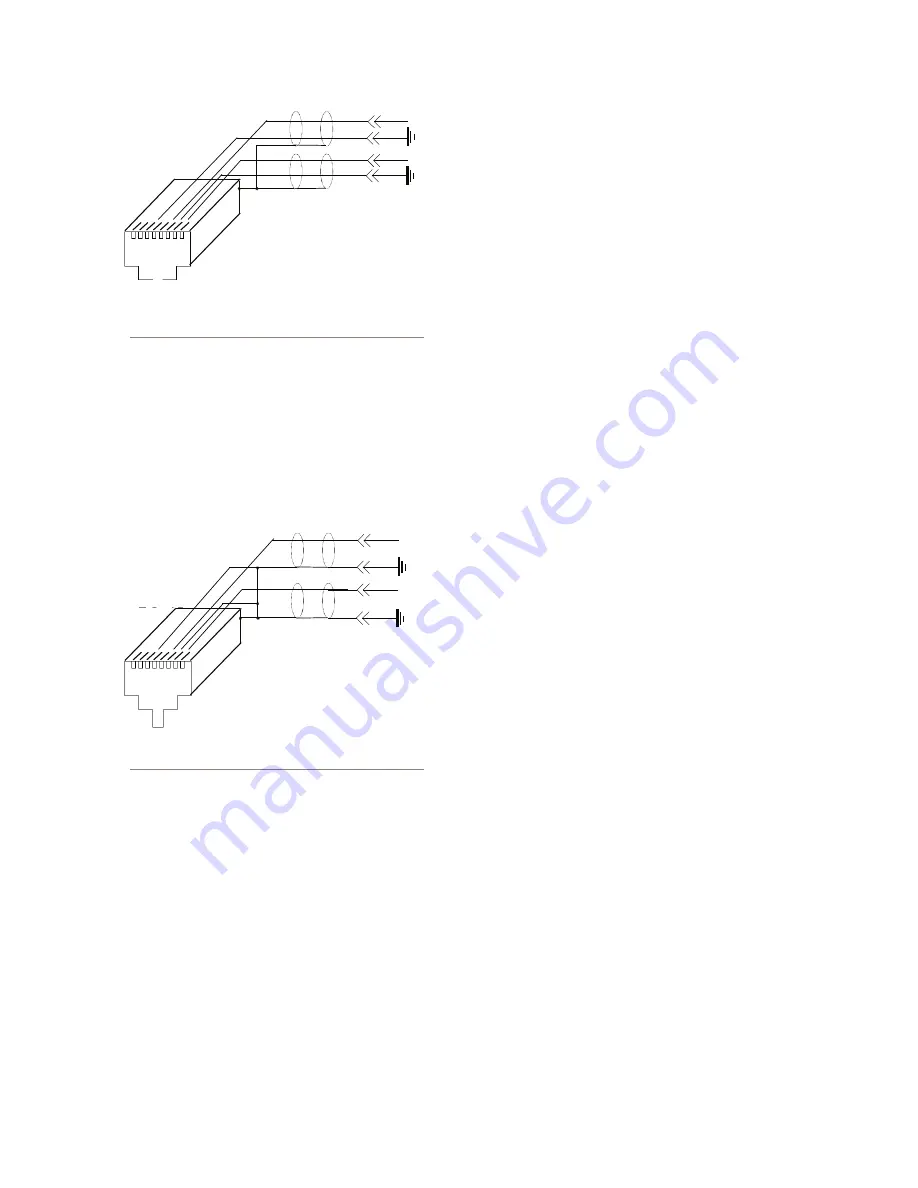
Axia node’s analog inputs fed from an unbalanced 

source where both pieces of equipment are tied to a 

facility ground.

Alternatively,  if  both  pieces  of  equipment  are  not 

both tied to a common facility ground, both sides of the 

shield must be connected. In this case the “-“ side of the 

nodes inputs are tied to the shield of the RJ-45 plug as 

follows:

Axia node’s inputs fed from a floating source, with no 

facility ground in common with the Axia node.

Using Axia Nodes with Ethernet 

Radios

Applies to Node Software v2.3.2a and higher

There are several changes and additions to Axia Au-

dio Nodes software beginning with v2.3.2a designed 

to simplify the operation of STLs and audio snakes 

using Axia nodes in conjunction with Ethernet Ra-

dios.

These additions include:

STL Slave and STL Snake modes on Clock Master 

Priority options

IP Low Rate is now set as the default receive Clock 

mode in the LW Clock Mode options field. (Note that 

this setting only defines the RECEIVE type of stream. 

It does not change the clock stream type when the 

node is acting as the Master Clock. We recommend 

that you do not change this setting.)

A Standard Stream Buffering option, which is set to 

100ms as default. (Note that this setting should not 

be adjusted unless advised otherwise by Axia Tech-

nical Support.)

A  “Master/Sync”  confidence  tally  is  added  to  the 

Router Selector Node display.

Using Axia Audio Nodes as snakes or STLs

Note that the setup options described below require 

that  Node  Software  v2.3.2a  or  higher  must  be  in-

stalled to work correctly.

OPTION 1 - Using two nodes back to back without 

an Ethernet switch

In  this  scenario,  the  clock  sync  mode  will  set  the 

Clock  Rate  to  a  Low  Rate  sync  packet  regardless 

of the Livewire Clock Mode setting. This enables a 

more stable SYNC mode, eliminating the need for an 

Ethernet switch between the nodes handling QOS of 

the clock sync signal.

Navigate  to  the  “QOS”  web  pages  of  the  Audio 

Nodes you’ll be using. Determine which one will be 

the master and which the slave, and set the new “STL 

Snake” and “STL Slave” clock priority modes to the 

appropriate values. 

Typically, you will set the Clock Master Priority op-

tion on the Node located in the studio to “7 (Always 

Master) STL Snake”. The Node on the remote end of 

the link should be set to “0 - (Always Slave) STL”. 

All  stream  types  must  be  set  to  Standard  streams. 

1

8

+

+

R

L

Содержание 8x8 AES Node

Страница 1: ...8x8 Analog Node 8x8 AES Node Installation User s Guide Version 2 0 February 2007...

Страница 2: ...limits for radio noise emissions set out in the Radio Interference Regulations of the Canadian Depart ment of Communications Le present appareil nu merique n emet pas de bruits radioelectriques depas...

Страница 3: ...ecome available to determine if this is the case check our web site Contact us to determine if a newer release is more suitable to your needs Our electronic newsletter has announcements of major softw...

Страница 4: ...t when you call so our Support Engineers can verify infor mation about your con guration and the conditions under which the problem occurs If the unit must return to Axia we will need your serial numb...

Страница 5: ...Programming the unit s Receive Base Channel RxBCH 7 Chapter Three Advanced Programming 9 Assigning an IP Address Remotely 9 Accessing the Node s Web Pages 9 The 8x8 node home page 10 The Con gure Sour...

Страница 6: ...one RJ 45 two way multiple audio channels sophisticated control and data capabil ity and built in computer compatibility You can use Livewire as a simple sound card replacement an audio interface conn...

Страница 7: ...er and console engine were now integrated but the most important studio ele ment the PC was stuck in the past interfaced with 100 year old analog technology The PC and console couldn t communicate in...

Страница 8: ...Introduction viii Version 2 0 February 2007...

Страница 9: ...ow the operator to verify proper operation quickly and con dently Status LED indicators Four LEDs indicate the status of the Livewire and Ethernet connections as well as system synchronisation as foll...

Страница 10: ...odes have a bargraph meter for each input and each output INPUT Transmit to network METERS The left eight meter pairs represent the left and right channels of each input The meters are continuously ac...

Страница 11: ...not enabled for multicast this will result in network congestion that could disrupt other network activity Should you wish to connect a node to a non Livewire network for access to the web con guratio...

Страница 12: ...ces are to be connected to these outputs we strongly rec ommend using a balanced to unbalanced buf fer ampli er or transformer at the destination device Such devices are readily available for example...

Страница 13: ...eration of the units When connected in this way the audio fed to input 1 of node A will be output on output 1 of node B whereas the audio on input 1 of node B will be output on output 1 of node A Like...

Страница 14: ...the Introduction to Livewire System Design Reference Primer manual for more on streaming The possible settings for stream ing mode are shown here 1 2 3 4 5 OFF This disables both streaming of Livewir...

Страница 15: ...streams to be received by this node and output from its audio connectors If the Receive Base Channel is set to 00201 then the system will search the Livewire network for eight streams on channel numb...

Страница 16: ...2 Operation Via the 8x8 s Front Panel 8 Version 2 0 February 2007...

Страница 17: ...re intended for use with an Ethernet Switch that supports mul ticast and QOS Quality of Service On a non switched Ethernet hub or a switch that is not enabled for multicast this will result in network...

Страница 18: ...be assigned a unique channel number The channel num ber must be a number between 1 and 32767 Optionally a text name can be entered Livewire names may contain any printable charac ter and can be up to...

Страница 19: ...nominal device that clips at some lower level for example 18 dBu e g 14 dB headroom you can increase the gain by 6 dB in our exam ple to match this device s clip point to the node s 0 dBfs point This...

Страница 20: ...following Select Source screen will be displayed see below You can now click on the name or channel number of the desired source to assign it to this Destination lo cal output If a Livestream e g a lo...

Страница 21: ...port multicast streams and will not work The Meters Page The Meters screen shown on the below is simply a metering screen that shows the audio level of all local sources local inputs and destinations...

Страница 22: ...is used to identify the node on the net work You may wish to include the location of the node studio and rack in the name for future reference Network address IP Address The IP address of the local un...

Страница 23: ...y higher than that speci ed by the l ter will be forwarded to the remote logger User password This is the password required to connect to the unit It must be at least 5 characters long and may be as l...

Страница 24: ...ite www axiaaudio com down loads and download the desired software update for your node to your computer this should be the computer that you will use to access the node s web page Your local computer...

Страница 25: ...t recommended setting Ethernet compatible with 1 x rmware IP High rate compatible with 2 1 x master Receive Bu er Size Determines the amount of buffering in the receiver Buffering is needed to compens...

Страница 26: ...when it becomes the Livewire master clock source If this node becomes the Livewire clock master see above then the entire Livewire network will be synchronized to the AES sig nal fed to the selected...

Страница 27: ...o network However if you are in a bind or otherwise determined to do so here is how we recommend connecting Axia nodes to unbalanced equip ment Unbalanced Destinations To feed audio to an unbalanced d...

Страница 28: ...ng as the Master Clock We recommend that you do not change this setting A Standard Stream Buffering option which is set to 100ms as default Note that this setting should not be adjusted unless advised...

Страница 29: ...ode running version 2 2 0 when op erating as the current Clock Master will generate two clock streams a High rate and a Low rate clock sync Nodes running version 2 1 x and earlier do not have this dua...

Страница 30: ...Appendices 22 Version 2 0 February 2007...

Страница 31: ...evel 4 dBu 20 dB FSD Impedance 110 Ohm balanced XLR Signal Format AES 3 AES EBU AES 3 Input Compliance 24 bit with selectable sample rate conversion 32 kHz to 96kHz input sample rate capable AES 3 Out...

Страница 32: ...ne channel to channel isolation 80 dB isolation minimum 20 Hz to 20 kHz Analog Line Stereo separation 85 dB isolation minimum 20Hz to 20 kHz Analog Line Input CMRR 60 dB 20 Hz to 20 kHz Microphone Inp...

Страница 33: ...for incidental or consequential damages or for loss damage or expense directly or indirectly arising from the use of any Product or the inability to use any Product either separately or in combinatio...

Страница 34: ...World now digital Analog memori fade The future b kons...

Страница 35: ...Axia Audio a Telos Company 2101 Superior Ave Cleveland Ohio 44114 USA 1 216 241 7225 www AxiaAudio com...

Отзывы: