background image

Some products may not be available in your country, please contact our distributor for more details

Some products may not be available in your country, please contact our distributor for more details

9

10

5.OPERATING THE SPEED DOME

FIRMWARE 
Protocol: PELCO
Dome Address: 001
Comm 9600,N,8,1

V1.03


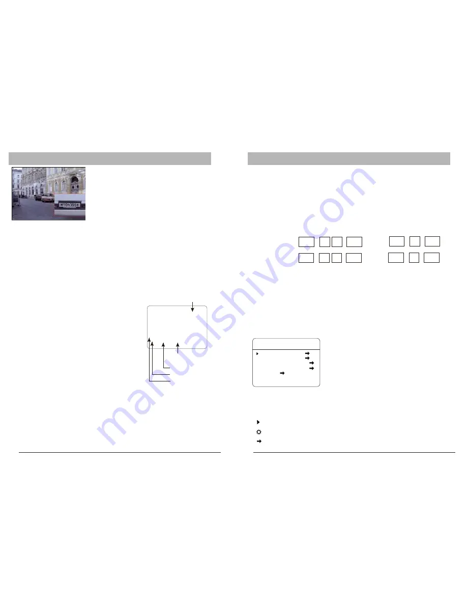
Initial Screen

After powering up, the camera will enter into 
the self-test mode and display the status 
screen (see picture left). It contains 
information about the model and current 
settings.

- “

 "

: Model number

- V1.03:

 Current firmware version

- Protocol:

 Control protocol which currently used

- Dome address:

 Address ID of speed dome. Please refer to the section "Protocol 

setup " for details

- Comm 9600,N,8,1: 

Current setting of the serial communication interface

9600:

 Baud rate. Please refer to section "Baud-Rate setup" for details

N, 8, 1:

 No parity bit, 8 bit length, 1 stop bit. This setting cannot be changed 

FIRMWARE

Operation  Screen

The operation screen can display additional 
information. 

Temperature: Current temperature inside the speed 

dome( °C)

Cam title:        User definable camera title
Zone:             Current zone name
Pan deg.:       Pan angle, 0-359°
Tilt deg.:         Tilt angle, 0-90°
Zoom Factor: Zoom factor

Display of the information can be activated or 

deactivated through the OSD menu.Pplease refer to 
the system setting for detais.

The intial screen will remain on until any user action is taken. If the power-up action is 
set, the initial info wil vanish immediately.

32.0

CAM TITLE

ZONE-1

285   78

18X

Pan degree

Zoom factor

Tilt degree

Zone description

Temperature

PTZ operation

 For the surveillance operation, the dome can be controlled from a keyboard device, 
Multiplexer or DVR  through RS485 interface. Make sure that the cable is connected 
and the settings (baud rate, Address ID and protocol) of both, keyboard and the dome, 
are correctly configurated. For further details on


operating the PTZ, please refer to the 

user’s manual of the keyboard.

OSD Menu

The dome camera are equipped with the new OSD Menu function. All operational functions 
and  camera related settings can be controlled here. In order to use the OSD function, a 
telemetric controller device, such as keyboard, DVR or other devices with similiar functions, 
is required. Please make sure that the device used is properly physically connected to the 
dome and all connection parameters are set. 

How to start the OSD Menu

To start the OSD Menu, you need to press the following sequence on the keyboard:

      With 

                                                             or  

2 X

      With keyboard                                                              or 

2 X

In case a DVR is used for operating  the OSD, select  “go to preset 95” or 2 X “go to preset 9”. 
Please refer to the DVR’s operation manual for more details.

Note that in some situations, it is not possible to access the OSD menu: 

1. The dome is running a tour
2. Performing PTZ operations
3. Dome is receiving a command other than OSD-request from the keyboard

To solve this inability stop the operation and try again.

keyboard


Shot

9

5

Enter

Main menu and navigation

Main Menu

SYSTEM  SETTING
CAMERA  SETTING
FUNCTION  SETTING
WINDOW  BLANKING
ALARM
EXIT

After entering the OSD Menu, the screen will show 
menu items . Use the controller’s  joystick to navigate 
the menu’s main and sub items by moving in the 
desired direction. The angle mark on the beginning of 
every item indicates the selection. 

UP, DOWN: 

- Moving between current menu items
- Changing the value in sub items

RIGHT: 

- Enter the selected menu item

- Confirm the value change and return 

to 

   item selection

LEFT: 

- Exit from sub menu

For more inforamtion, please refer to the illustration on 

Symbols and indicator

Cursor.

Sub item is selected. use up or down to change value

This item has subitem(s)

call

9

5

Enter

call

9

Enter

Shot

9

Enter

6.OSD

(

)

3-Axis

Содержание G40

Страница 1: ...User Manual English v1 03 Middle Speed Dome Camera Series ...

Страница 2: ... BE REQUIRED TO CORRECT THE INTERFERENCE AT HIS OWN EXPENSE WARNING THIS IS A CLASS A PRODUCT IN A DOMESTIC ENVIRONMENT THIS PRODUCT MAY CAUSE RADIO INTERFERENCE IN WHICH CASE THE USER MAY BE REQUIRED TO TAKE ADEQUATE MEASURES CAUTION TO REDUCE THE RISK OF ELECTRIC SHOCK DO NOT REMOVE COVER OR BACK NO USER SERVICEABLE PARTS INSIDE JUST QUALIFIED SERVICE PERSONNEL SHOULD SERIVICE THE PRODUCT This s...

Страница 3: ...s this may damage the mechanic sturcture of the appliance and voids the warranty Do not touch the cover with bare hands or any objects These will scratch the surface and negatively affect the image qulaity 2 FEATURES The middle speed dome camera series are designed for video surveillance applications The integrated motorized pan tilt mechanic allows users to maneuver the camera to any position 360...

Страница 4: ...g protection and grounding of the device should be considered Please refer to the industrial saftey regulations of your country Grounding of the appliance should include anti interference and fulfill the safety requirements Do not connect the ground with short circuited or other high voltage electric networks The resistance of down conductor should not exceed 4 Ohm and its thickness should be at l...

Страница 5: ...logy Depending on the cable type and baud rate the transmission distance could vary The following table shows max distances based on cable with 0 56mm 24AWG twisted pair 2400 bps 1100 m 700m 400m 4800 bps 1700m 9600 bps 19200 bps Baud Rate Max Distance Due the environmental interferences such as eletromagnetic and induction fields or number of connected appliance on the RS485 bus the transmission ...

Страница 6: ...Star Connection The star form connection is a popular way to connect different devices It enables longer distance connection of different dome cameras It is recommended to use RS485 distributor to ensure the telemetric data transmission The advantage of star connection is that every channel can work independently and supports a cable length up to 1000 meters depending on the quality of the cable I...

Страница 7: ...aud rate Address ID and protocol of both keyboard and the dome are correctly configurated For further details on operating the PTZ please refer to the user s manual of the keyboard OSD Menu The dome camera are equipped with the new OSD Menu function All operational functions and camera related settings can be controlled here In order to use the OSD function a telemetric controller device such as k...

Страница 8: ...P R E S E T C L E A R P R E S E T E D I T P R E S E T L A B E L B A C K E X I T L A B E L P R E S E T 0 1 B A C K E X I T E D I T P R E S E T L A B E L L A B E L A U T O S C A N B A C K E X I T EDIT SCAN LABEL L A B E L P A T T E R N 1 B A C K E X I T EDIT PATTERN LABEL L A B E L Z O N E 1 B A C K E X I T EDIT ZONE LABEL L A B E L S P E E D D O M E B A C K E X I T 1 00 E D I T D O M E L A B E L D ...

Страница 9: ...CK EXIT 6 OSD Camera Setting ADVANCE SETTING AE MODE AUTO SHUTTER N A IRIS N A BRIGHT N A WB MODE AUTO R GAIN N A B GAIN N A BACK EXIT Advanced Setting Under the advanced setting you can make improvements tothe image quality depending on different environmental conditions AE MODE Auto Exposure mode Depends on the light condition in the surveillance area you can set the AE in different modes and ad...

Страница 10: ...P R E S E T C L E A R P R E S E T E D I T P R E S E T L A B E L B A C K EXIT Scan The SCAN function moves the PTZ between 2 predefined points with constant speed The following parameters can be set SCAN NUMBER Supports up to 4 scans SCAN SPEED Cruising speed between the points SET LEFT LIMIT Defines the left point SET RIGHT LIMIT Defines the right point CLEAR SCAN Deletes the scan setting RUN SCAN...

Страница 11: ...a modules up to 24 masking areas except the 45 series provides only 8 LG CNB Camera modules no masking function WINDOW NUMBER Mask number EDIT WINDOW Edit position of the mask using the keyboard s joystick Presse IRIS OPEN to save ENABLE WINDOW Shows the mask on the screen CLEAR WINDOW Deletes the mask WINDOW BLANKING WINDOW NUMBER 01 EDIT WINDOW ENABLE WINDOW OFF CLEAR WINDOW BACK EXIT 7 PROTOCOL...

Страница 12: ...1 1 1 0 0 0 0 0 41 1 0 0 1 0 1 0 0 ID ID 0 0 0 0 0 0 0 0 0 1 0 0 0 1 0 0 34 Some products may not be available in your country please contact our distributor for more details 102 103 104 105 106 107 108 109 110 111 112 113 114 115 116 117 118 119 120 121 122 123 124 125 126 127 128 129 130 131 132 133 134 135 101 100 99 98 96 97 95 94 93 92 91 90 89 87 88 86 85 84 83 82 72 81 80 79 78 77 76 75 74 ...

Страница 13: ... 0 0 0 1 0 1 1 0 1 0 0 0 1 1 0 0 1 0 0 1 0 1 0 1 1 0 0 0 1 1 1 0 1 0 0 1 0 1 1 1 1 0 0 0 1 1 0 1 1 0 0 1 0 1 0 0 0 1 0 0 1 1 1 1 1 0 0 1 0 1 1 0 0 1 0 0 1 1 0 0 0 1 0 1 0 1 0 1 0 1 0 0 1 1 1 0 0 1 0 1 0 1 1 1 0 1 0 0 1 1 ID ID Switchnumber Sw1 Switchnumber Sw1 Some products may not be available in your country please contact our distributor for more details 237 236 235 234 233 255 254 253 252 251 ...

Страница 14: ...ua Auto Slow Shutter LOW MEDIUN HIGH MANUAL OFF CVBS 1 0Vp p 75Ω 0 100 per Sec Shutter Speed 1 to 1 10 000 Sec 1 3 to 1 10 000 Sec Focus White Balance Auto Manual Auto Manual ATW Indoor Outdoor One Push WB Manual WB Viewing Angle Image Sensor 1 4 inch super HAD color CCD Model Signal Format Scanning PAL NTSC 2 1 Interlace H Resolution 550 TV Lines Min Color 680 TV Lines Min B W H Appr 55 5 Wide to...

Отзывы: