background image


953.160UK User Manual 
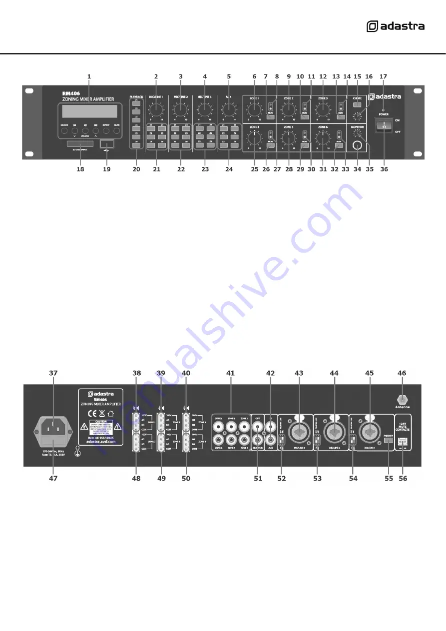
Front panel 


Rear panel 


1. 

Media player  

19.  USB port 

2. 

Mic/Line 1 level control 

20.  Media playback zone assign buttons 

3. 

Mic/Line 2 level control 

21.  Mic/Line 1 zone assign buttons 

4. 

Mic/Line 3 level control 

22.  Mic/Line 2 zone assign buttons 

5. 

Auxiliary line input level control 

23.  Mic/Line 3 zone assign buttons 

6. 

Zone 1 output level control 

24.  Auxiliary line input zone assign buttons 

7. 

Zone 1 monitor send button 

25.  Zone 4 output level control 

8. 

Zone 1 output LED indicators 

26.  Zone 4 monitor send button 

9. 

Zone 2 output level control 

27.  Zone 4 output LED indicators 

10. 

Zone 2 monitor send button 

28.  Zone 5 output level control 

11. 

Zone 2 output LED indicators 

29.  Zone 5 monitor send button 

12. 

Zone 3 output level control 

30.  Zone 5 output LED indicators 

13. 

Zone 3 monitor send button 

31.  Zone 6 output level control 

14. 

Zone 3 output LED indicators 

32.  Zone 6 monitor send button 

15. 

Chime button 

33.  Zone 6 output LED indicators 

16. 

Chime output level control 

34.  Monitor headphones output 

17. 

Power indicator 

35.  Monitor output level control 

18. 

SD card slot 

36.  Power on/off switch 

37. 

Voltage selector  

47.  Mains power inlet (IEC) and fuse holder 

38. 

Zone 1 speaker output terminals 

48.  Zone 2 speaker output terminals 

39. 

Zone 3 speaker output terminals


49.  Zone 4 speaker output terminals


40. 

Zone 5 speaker output terminals


50.  Zone 6 speaker output terminals


41. 

Zones 1-6 line level outputs (RCA) 

51.  Monitor line level output (2 x RCA) 

42. 

Channel 4 Auxiliary input (2 x RCA) 

52.  Channel 3 DIP switches (mic/line + phantom) 

43. 

Channel 3 Mic/Line input (XLR/jack) 

53.  Channel 2 DIP switches (mic/line + phantom)


44. 

Channel 2 Mic/Line input (XLR/jack)


54.  Channel 1 DIP switches (mic/line + phantom)


45 

Channel 1 Mic/Line input (XLR/jack)


55.  Channel 1 priority switch 

46. 

Antenna connection 

56.  24V emergency mute contacts 

Содержание Adastra RM406

Страница 1: ...RM406 Rackmount 6 zone Mixer Amplifier Item ref 953 160UK User Manual Version 1 1 Caution Please read this manual carefully before operating Damage caused by misuse is not covered by the warranty ...

Страница 2: ...arning symbols during transit and placement 14 Terminals marked with the symbol are HAZARDOUS LIVE and should only be connected by qualified personnel 15 Ensure that the apparatus is connected to a mains socket with a protective EARTH connection 16 Ensure correct operation of the mains switch Warning To prevent the risk of fire or electric shock do not expose any components to rain or moisture If ...

Страница 3: ...utton 31 Zone 6 output level control 14 Zone 3 output LED indicators 32 Zone 6 monitor send button 15 Chime button 33 Zone 6 output LED indicators 16 Chime output level control 34 Monitor headphones output 17 Power indicator 35 Monitor output level control 18 SD card slot 36 Power on off switch 37 Voltage selector 47 Mains power inlet IEC and fuse holder 38 Zone 1 speaker output terminals 48 Zone ...

Страница 4: ...ifier is switched off Making any changes when the amplifier is powered up may cause loud bangs through the system which can damage the speakers Priority and Emergency Activation The Mic Line 1 input also has a Priority switch 55 which attenuates all other channels when Mic Line 1 signal is detected and returns them to normal when Mic Line 1 signal is silent For buildings with a main emergency alar...

Страница 5: ...t is advised to connect as many speakers as needed with a combined wattage of no more than 90 of the amplifier s output power rating in the case of the RM406 this is 40W per zone output The terminals of a 100V speaker are connected via a transformer and if necessary this transformer may be tapped for different power ratings These tappings can be used to adjust the wattage and output volume of each...

Страница 6: ...he green LED follows the audio to show that the signal is present If the red LED lights for more than very short flashes this indicates overload to that zone In this instance the zone level control should be reduced until the red LED does not light The above process can be extended to check all zones and other input channels can be checked in the same way as for Mic Line 1 note in the case of Aux ...

Страница 7: ... necessary to connect an external aerial to the Antenna connector on the rear panel using good quality coaxial RF cable terminated with an F type connector To auto tune available stations press and hold the Play Pause button to begin auto tuning which scans available stations and automatically stores them as channels within the FM tuner Alternatively to tune the station presets manually press the ...

Страница 8: ...audio from media Press Play Pause button to check if track is paused Press the Source button to ensure that the required device is selected Check memory device is connected properly remove and re insert Check file types standard compressed digital audio files are required Check memory device works on a PC or Mac for standard playback Output is very loud or distorted Check level of input signal is ...

Отзывы: