AVLink HRM-602P Скачать руководство пользователя страница 10

H

H

H

R

R

R

M

M

M

-

-

-

6

6

6

0

0

0

2

2

2

P

P

P


CHAPTER 4 DEVICE INSTALLATION 

The Switcher has a black metallic housing. It can be placed on a sturdy desk directly or 

installed on a bracket. See Figure 4-1 below: 


Figure 4-1 Mount the Device on a Standard Bracket with 1U Rack-mount 

CHAPTER 5 FRONT/REAR PANELS 

5.1 Front Panel 


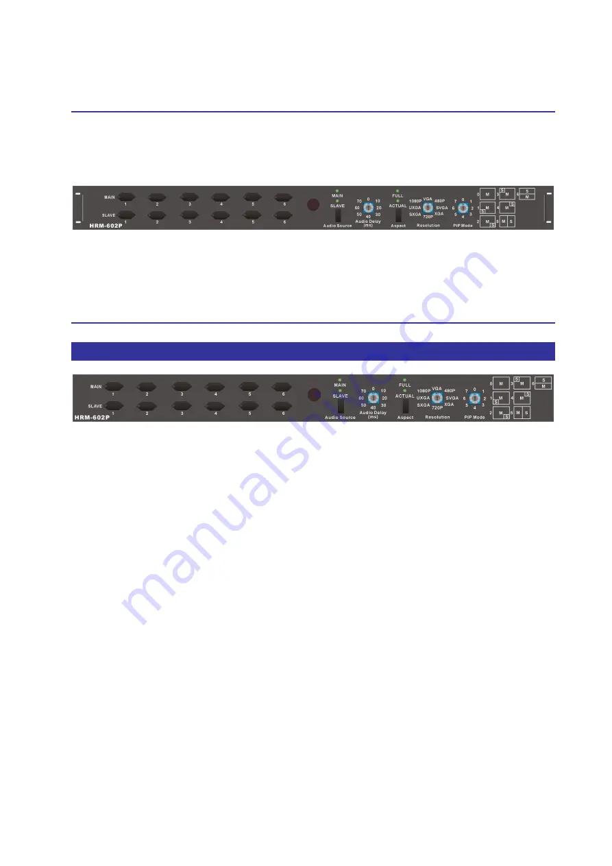
Figure 5-1 HRM-602P Switcher Front Panel 

The  HRM-602P  Switcher  supports  up  to  12  switching  keys  on  the  Front  Panel  for 

indicating the connection status of the Main or Slave window that allows you to switch 

each screen quickly. 


MAIN 1~6 keys 

(Main window)

:

 Specifies the one of input HDMI1~ HDMI6 channel to 

a  Main  window  output.  These  keys  configure  the  signal  sources  of  HDMI1~HDMI6 

channels upon the Main window. You can also use these keys to switch input channels. 


SLAVE 1~6 keys

 (Slave window)

:

 Specifies the one of input HDMI1~ HDMI6 channel 

to a Slave window output. These keys configure the signal sources of HDMI1~HDMI6 

channels  upon  the  Slave  window.  You  can  also  use  these  keys  to  switch  input 

channels. 


Audio  Source  key:

  Press  this  key  to  switch  the  audio  source  comes  from  the  main 

window or slave window.   

-

  MAIN LED indicator:

 When the input channel for the Main window is selected 

as the audio source, the MAIN LED indicator will become solid green.   

Содержание HRM-602P

Страница 1: ...H H H R R R M M M 6 6 6 0 0 0 2 2 2 P P P 0 User Manual Seamless HDMI Switch Scaler with PIP and Audio Delay Functionality 6x2 HRM 602P V 2013HRM 602P 00...

Страница 2: ...s without written permission from the product manufacturer Changes are periodically made to the information in this document They will be incorporated in subsequent editions The product manufacturer m...

Страница 3: ...stable before extending a device from the rack Make sure all equipments installed on the rack including power strips and other electrical connectors are properly grounded Only use the power cord suppo...

Страница 4: ...I Switcher System Remote Control 18 6 3 IR EXT Connection 19 6 4 Power Connection 19 6 5 Ports and Switchers 20 6 5 1 RS 232 20 6 5 2 LAN Port 22 6 5 3 DIP Switcher 8 Pins 22 6 5 4 Device ID Settings...

Страница 5: ...8 Appendix A IR Controller 40 Appendix B Firmware Upgrade 42 Appendix C RS 232 Communication Protocol 45 D 1 Host Request 45 D 1 1 Device Byte 45 D 1 2 Request Byte 46 D 1 3 Index Byte 48 D 1 4 Value...

Страница 6: ...s used mainly in TV broadcasting projects multimedia conference halls and large display performances TV teaching and command control centers It boasts features of power interruption protection during...

Страница 7: ...6 1 2 Packing HRM 602P Switcher 1 RS 232 Communication Connected Cable 1 Power Cord 1 Adapter 1 HDMI Cable 1 Rack Mount Bracket 2 Screws for Brackets 6 IR Remote Controller 1 Software CD 1 Includes A...

Страница 8: ...pect ratio modes Actual 1 1 Aspect ratio mode This mode keeps the output image have the horizontal and vertical ratio as same as the input image comes from the video That makes the output image has no...

Страница 9: ...specified for the connection is Selected Adapter INPUT 100VAC 240VAC 50 60Hz 1 5A OUTPUT 12V 5A Housing Metal Mounting Rack mountable 1U rack mount kit Weight 1 8kg Dimensions LxWxH 384x173x45 mm Mult...

Страница 10: ...creen quickly MAIN 1 6 keys Main window Specifies the one of input HDMI1 HDMI6 channel to a Main window output These keys configure the signal sources of HDMI1 HDMI6 channels upon the Main window You...

Страница 11: ...ttings Usually when you process the video images at times it can take longer than processing the audio signal The longer processing time is called latency Audio Delay feature is designed to correct fo...

Страница 12: ...tions It can transform the input source to available output resolution PIP Mode PIP picture in picture is a feature that allows the screen to display more than one image Depending on this feature you...

Страница 13: ...els simultaneously Each of them is assigned to Main or Slave window individually PBP Mode The PBP Mode is split the screen into two equal pictures The picture on the left side of your screen is the Ma...

Страница 14: ...2 P P P 13 For PBP Mode you have to adjust the PIP Mode located on the front panel of HRM 602P Switcher to No 5 or 6 7 The PIP Mode No 7 is the same as No 6 Figure 5 6 PIP Display for PBP Mode 5 Figur...

Страница 15: ...eive the signals is about 12 meters Figure 5 8 IR Receiving Distance 5 2 IR Remote Controller Figure 5 9 IR Remote Controller Main Channel Port selection Press the Number 1 6 button to select the chan...

Страница 16: ...minals supply you to connect to different equipments including CD DVD players Blue Ray player PS3 Video Camera STB and so on The output terminal with HDMI and VGA interface can be connected to project...

Страница 17: ...he computer can then be deployed to control the HRM 602P after installing of application software Refer to 7 1 Software Introduction for a software control or Appendix C RS 232 Communication Protocol...

Страница 18: ...ut Connections Use the HDMI connecting cable to connect the Input HDMI connector HDMI 1 HDMI 6 to the HDMI connector of the CD DVD player Camera PS3 STB PC and output connector HDMI OUT to the HDMI co...

Страница 19: ...n software Aside from using the front panel keys for switching operation you are also permitted to use the RS 232 connection port for a remote operation Figure 6 4 RS 232 and Control PC connection The...

Страница 20: ...difficult for you to aim at IR receiver on the front panel due to the location of Switcher please connect it to the IR EXT port located on the rear panel for optional position Figure 6 6 IR Extended...

Страница 21: ...eside the front panel for key switching operation you can also use the RS 232 serial communication port to carry out remote operation 6 5 1 RS 232 The RS 232 Pin functions are described as below Pin N...

Страница 22: ...H H H R R R M M M 6 6 6 0 0 0 2 2 2 P P P 21 Figure 6 8 b Figure 6 9 The Switcher RS 232 port is defined by DCE...

Страница 23: ...ble is available Figure 6 10 LAN Port 6 5 3 DIP Switcher 8 Pins Figure 6 11 DIP Switch A DIP Switcher Pin 1 Reset the web server IP address to 192 168 0 3 The steps are as below 1 Please adjust the pi...

Страница 24: ...is to be controlled Device ID must not set to same number Use the ON OFF switches 1 2 3 4 5 on the rear panel to set the ID number as below Number Setting Table ON OFF Switching Positions ID Address D...

Страница 25: ...0 14 10100 OFF ON OFF ON ON 21 15 10101 OFF ON OFF ON OFF 22 16 10110 OFF ON OFF OFF ON 23 17 10111 OFF ON OFF OFF OFF 24 18 11000 OFF OFF ON ON ON 25 19 11001 OFF OFF ON ON OFF 26 1A 11010 OFF OFF ON...

Страница 26: ...oped for matrix testing and application The software operation environment is as below Window98 2000 NT XP operating systems 32M internal memory or above 10M hard disk space or above CD ROM At least o...

Страница 27: ...set to Master and RS 232 Refer to the previous section 6 5 1 RS 232 7 2 Switcher Configuration After finishing installation click to active AV Matrix Application In the Options window select the conne...

Страница 28: ...ng functions Example Now there is an HRM 602P Switcher having all the input output ports properly connected to the equipment If you want to set channel 1 input to channel 2 3 and 4 output channel 3 in...

Страница 29: ...t and output ports you can click this button to disable the connections Select all output Click this button to select all output ports including output 001 016 Video check box Used for video configura...

Страница 30: ...P P P 29 7 2 2 Disconnect Function Key Disable all the unused output ports A specific example of operation is described as below The present input and output relations are shown in Figure 7 4 a below...

Страница 31: ...Port number select one of the COM ports as shown in Figure 7 5 b for a example in Baud rate select 9600 for signal transmission as shown in Figure 7 5 a 7 2 4 Communication Protocol Control Command Co...

Страница 32: ...ice ID is based on the DIP of switcher located on the rear panel Set Click this button to set the connected combinations both output and input ports OFF Disable the entire output channels Refresh To r...

Страница 33: ...to all output channels Select the All Output check box then key in example 5 value in the channel 1 output Click anywhere on the window the all channels output will become 5 value Figure 7 7 All Outpu...

Страница 34: ...switch to Default alternately it will appear OUT1 with Output1 selection If the Switcher does not support video function it will appear Not Support The Change button will useless Figure 7 10 Video Co...

Страница 35: ...as below In PIP mode 0 only output 1 is available Switch channel In PIP mode 1 6 Output 1 is Main channel of the HRM 602P Output 2 is Slave channel of the HRM 602P Example Now there is an HRM 602P Sw...

Страница 36: ...Step 2 For channel 2 Output please key in the value 3 in the Vide fields Step 3 Click Set button Upon completion of the above 3 steps you have actually completed the switching operation of having cha...

Страница 37: ...Figure 7 14 Network Settings In the Network Settings window you can set the IP information by yourself Fix IP or click the Enable DHCP check box to get the IP from the DHCP Float IP Click the Default...

Страница 38: ...alues The entire connected Device name will be showed on the Console List as Figure 7 15 For this model the software utility will show at least 1 up to 32 devices The example as below shows you an ID...

Страница 39: ...rial port of the equipment Also check if the computer communication port is in good order Check the ID address and DIP Switcher are configured correctly Refer to 6 5 4 Device ID Settings 4 What to do...

Страница 40: ...re of the product please send for repair by qualified technical engineer 7 What to do if operation and function failure occurred Answer Check if the equipment and the Switcher system are in proper con...

Страница 41: ...ansmitter The signal for controller is only available to the IR receiver connected to the IR hole located on the rear panel Main Channel Port selection Press the Number 1 6 button to select the channe...

Страница 42: ...R M M M 6 6 6 0 0 0 2 2 2 P P P 41 Example Press the 0 button on the Remote controller first then press the 3 button to select the channel 3 input signal to the Slave channel Only available with PIP...

Страница 43: ...to your device from web server Follow the steps as below to upgrade the firmware 1 Open the Browser on your PC key in the default IP address http 192 168 0 3 to login the AV MA TRIX Control configurat...

Страница 44: ...ID 0 will be upgraded 4 For 1 Switcher Device will allow you to select target device based on ID 0 to 31 for upgrading firmware 5 Select 2 Switcher I O Module will allow you to upgrade I O modules Yo...

Страница 45: ...en though the web connection is fail suddenly Please check with the LCD screen to confirm the firmware upgrade has been finished successfully or wait at least 2 minutes then power off to restart your...

Страница 46: ...cher device via RS 232 Aside from using the front panel keys for operation you are also permitted to use the RS 232 connection port for remote operation D 1 Host Request A standard command is 5 bytes...

Страница 47: ...h Audio Output Channel Output Input A 2 0x03 Store Video Status Setting Memory A 2 3 0x04 Store Audio Status Setting Memory A 2 3 0x05 Recall Video Status Setting Memory A 2 0x06 Recall Audio Status S...

Страница 48: ...equest Audio Output Delay Low Output Memory B 0X1E Control Audio Output Delay High Output Delay2 A 2 0X1F Request Audio Output Delay High Output Memory B Video Control 0x20 Select Input EDID Type 0 ED...

Страница 49: ...t Request List and Table Command Index List Table Command Index List Index Description Output The output that will be selected Port 1 1 Port 2 2 Port n n 0 All outputs Input The input that will be sel...

Страница 50: ...ent Status Can t be stored Enable 1 Enable Status example Mute Plug 0 Disable Status example Unmute Unplug Level Level Range 0 100 0x81 Increase a step 0x82 Decrease a step Delay Audio delay time is 1...

Страница 51: ...3B D9 87 04 5A B8 E6 A7 F9 1B 45 C6 98 7A 24 70 F8 A6 44 1A 99 C7 25 7B 3A 64 86 D8 5B 05 E7 B9 80 8C D2 30 6E ED B3 51 0F 4E 10 F2 AC 2F 71 93 CD 90 11 4F AD F3 70 2E CC 92 D3 8D 6F 31 B2 EC 0E 50 A...

Страница 52: ...e 6 Last Byte Type A AB CB Type B AB LB Index 1 Value 1 Index 2 Value 2 CB Type C AB LB Data 1 Data 2 CB Type D AB LB INF OP IP Name 1 CB Type E AB LB EXINF VEINF AEINF PLUG CB D 2 1 ACK Type A ACK By...

Страница 53: ...B Response the status refers to the table Request Description Index Value 0x07 Request Video Output Channel 0x08 Request Audio Output Channel Output Input 0x09 Request Video Input Plug Status 0x0A Req...

Страница 54: ...RA VERB VERC Version Type A RS 232 Protocol Version contains the VER1 and VER2 ex VER1 VER2 VER1 Data 1 Bit 7 Bit 0 Range 0 99 VER2 Data 2 Bit 7 Bit 0 Range 0 99 If the Data 1 is 0x01 and Data 2 is 0x...

Страница 55: ...the data bytes not include the AB LB and CB The maximum LB value of the ACK Type D is 19 INFO Device information Bit 7 1 Support Audio switch tools request Request 0x02 0x04 0x06 and 0x08 0 Not suppor...

Страница 56: ...the maximum LB value of the variable length command 0 The maximum LB is 64 Bytes default 1 The maximum LB is 128 Bytes 2 The maximum LB is 254 Bytes 255 is reserved 3 Reserved The LB value of the Ack...

Страница 57: ...unit is 5ms default If the AEINF is not equal to 0 the device support Request 0x04 0x02 and 0x06 0x02 PLUG Plug Detect Support Information VIPD Video input plug detection command flag Request 0x09 1...

Отзывы: