background image


SkyEdgeII Modem


2.3.


Hardware Connection 

Connect the AAQ antenna controller to the SkyEdge II modem through the desired means.  The AAQ controller 
supports serial (RS232) and Ethernet communications to the modem and can be configured to use either depending on 
the necessary networking scheme.   


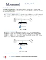
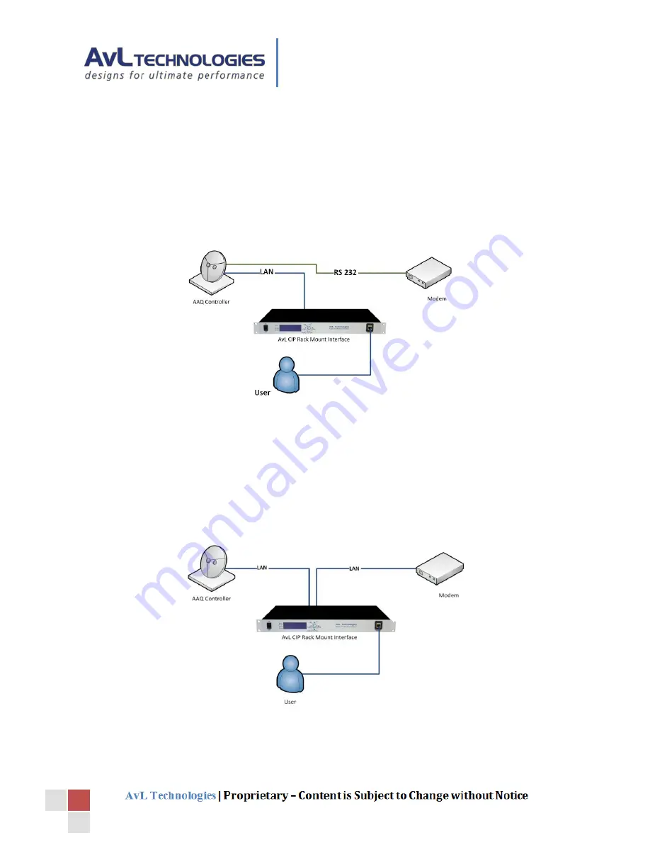
Serial Communication Connection 

2.3.1.

The interfacing occurs via RS232 serial port connected to the antenna at 9600-N-8-1 baud without any authentication 
or encryption in the link.  Refer to section 3.1 for settings.  To enable interfacing, it is not required to log in to the 
SkyEdgeII modem. 


Figure 2 – Serial Setup 


Ethernet Hardware Setup 

2.3.2.

When setting the system to communicate by Ethernet it an Ethernet to Serial server must be used. The AAQ 
Controller will be connected to the port labeled AAQ on the AvL CIP (Controller Interface Panel). The Ethernet 
connection from the Ethernet to Serial server will be connected to one of the LAN ports on the CIP. The Serial 
connection from the Ethernet to Serial server will connect to the Serial port on the back of the modem.  To enable 
interfacing, it is not required to log in to the SkyEdgeII modem.  


Figure 3 – Ethernet Setup 

Note:  Be sure to connect power to each device. 

Содержание SkyEdgeII

Страница 1: ...ide and Reference Revision R11 9 0 Documentation of the interface between the SkyEdgeII modem and the AvL Technologies AAQ antenna controller reference information and troubleshooting guide Appendix R AvL Technologies 900 159 017 ...

Страница 2: ... Updates for 11 8 4 19 17 R11 9 0 WL JF Updates for 11 9 and new template Contents 1 Introduction 2 2 Setup Guide 3 2 1 Hardware 3 2 2 Software 3 2 3 Hardware Connection 4 Serial Communication Connection 4 2 3 1 Ethernet Hardware Setup 4 2 3 2 3 Configuration 5 3 1 Core Configuration 5 3 2 Target Configuration 7 3 3 Signal Configuration 7 3 4 Feed Configuration 7 4 Operation 8 4 1 Functional Overv...

Страница 3: ...Figure 6 Configuration Target 7 Figure 7 Sensor Output 8 Figure 8 Device Window 9 1 Introduction The SkyEdgeII Modem is a compact design two way router and modem with DVB standards extensive IP capabilities embedded TCP HTTP and VPN acceleration This document describes the concepts required to use the SkyEdgeII module as part of the AAQ Controller In addition this document covers common issues and...

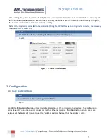
Страница 4: ...rdware is required for the operation of this module SkyEdge II Modem AvL AAQ Antenna System 2 2 Software Path Main Window Help Version Info Level 0 Be sure that the Remote Client ROM and device module are at or above the versions shown below Figure 1 Version Info ...

Страница 5: ...tings To enable interfacing it is not required to log in to the SkyEdgeII modem Figure 2 Serial Setup Ethernet Hardware Setup 2 3 2 When setting the system to communicate by Ethernet it an Ethernet to Serial server must be used The AAQ Controller will be connected to the port labeled AAQ on the AvL CIP Controller Interface Panel The Ethernet connection from the Ethernet to Serial server will be co...

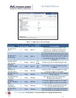
Страница 6: ...een configured as a router the Gateway must be set to 192 168 129 1 Path Main Window File Settings AAQ Network Interface Options Level 1 Figure 4 Advanced Network Settings 3 Configuration 3 1 Core Configuration Path Main Window View Configuration Core Level 4 Modify the following configuration items to enable interaction of the controller to the modem The configuration varies depending upon the ph...

Страница 7: ...l noise SkyEdgeII Gradient Sample Time 4 Integer System 0 to 60 Sample time in seconds for detecting signal gradient SkyEdgeII Lat Long Send Time 4 String Modules Amount of time in seconds between sending lat long messages to the modem SkyEdgeII Manual Latitude 1 String Modules The Latitude sent to the modem when SkyEdgeII GPS Override is 1 SkyEdgeII Manual Longitude 1 String Modules The Longitude...

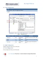
Страница 8: ...al Sources The signal source used for the initial target scan Coarse Source 1 Choice Installed Signal Sources The signal source used for the Coarse Scan process Fine Source 1 Choice Installed Signal Sources The signal source used for the Fine Scan process 3 3 Signal Configuration No Signal configuration items exist for this module 3 4 Feed Configuration No Feed configuration items exist for this m...

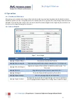
Страница 9: ... Figure 7 Sensor Output Item Description SkyEdgeII Detected Noise Noise level as reported by the AAQ SkyEdgeII Min Lock Signal Signal Level required for the modem to declare lock For future use SkyEdgeII Min Valid Signal Signal Level required from modem for AAQ to be able to peak For future use SkyEdgeII Rx Lock Flag indicating that the modem is locked on carrier SkyEdgeII Rx Signal This is the Do...

Страница 10: ...t the modem has locked on the carrier Downlink SNR This displays the Signal To Noise ratio signal strength of the locked carrier Downlink Center Frequency This displays the center frequency of the locked carrier Tx Enabled Flag indicating whether the transmit chain has been enabled by the modem Lat Long Sent Local indication of the position of the terminal to be sent to the hub equipment Logic Tab...

Страница 11: ... Serial or Ethernet cables and connections Does not find Target satellite Error popup during acquire process Acquire Failed Waiting For Device Signal Check that the AAQ is communicating with the Modem Check all RF cables and connections Check that the Target satellite is correct Check that the terminal heading latitude and longitude are correct Does not Peak on Target satellite Error popup during ...

Отзывы: