2. INSTALLATION
A. Connect the inlet flange with the water main. To prevent pipe joint separation restrain the movement of the
hydrant with appropriate thrust blocking or with restraining joints. Make sure the soil is compact around the
barrel to support the lower barrel against side loading. If the soil is too sandy and does not support the loads,
the barrel can be supported by pouring a concrete pad of at least 6 inches in thickness and 24 inches in
diameter around the barrel at or near the bury line.
To provide drainage, place clean coarse gravel or crushed stone from the bottom of the trench to at least 6
inches above the drain opening in the hydrant and to a distance of 1 foot around the elbow. For clay or other
impervious soils, excavate a drainage sump 2 feet in diameter and 3 feet deep below each hydrant. Fill the
sump with clean coarse gravel or crushed stone to a level of 6 inches above the drain opening.
Place a plastic sheet over the gravel to prevent dirt from clogging the drains.
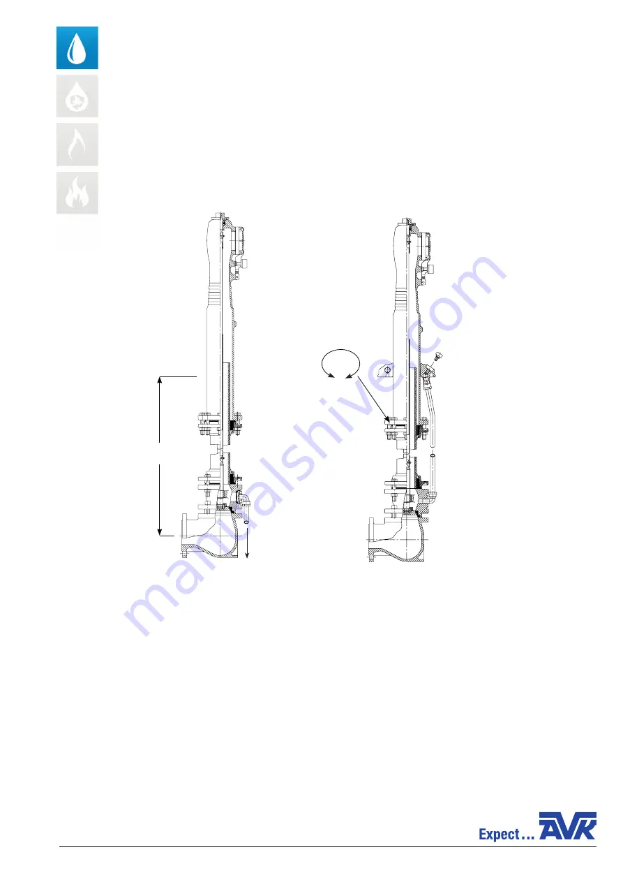
B. The ground cover can be placed above ground level since the hydrant is height adjustable and the outlet can
be placed in any requested position because of the 360° rotatable upper barrel.
When you assemble the upper part of the hydrant of the last 200 mm of the riser pipe from the lower part, a
support bush must be fitted – request this separately (see datasheet 05-E-008 for specification of bush).
COPYRIGHT©AVK GROUP A/S 2020 - AVK INTERNATIONAL A/S, Bizonvej 1, DK-8464 Galten - www.avkvalves.eu
9632500054 _rev AD_UK
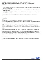
INSTALLATION & MAINTENANCE INSTRUCTIONS - ORIGINAL VERSION
AVK ABOVE GROUND FIRE HYDRANT, TYPE A & B, DN80/DN100
SERIES 09
Max. operation pressure: 10 bar
Max. operating temperature: 20°C
1. TECHNICAL DATA
Manual drainage
Automatic drainage
for fascine
Height adjustable
1050-1550mm
360°
rotatable


