background image

ScanCopier


8-2

8.2 LUBRICANTS

This section describes the items to check and the places to lubricate when maintenance parts are
replaced.

8.2.1 MECHANICAL UNIT LUBRICATION

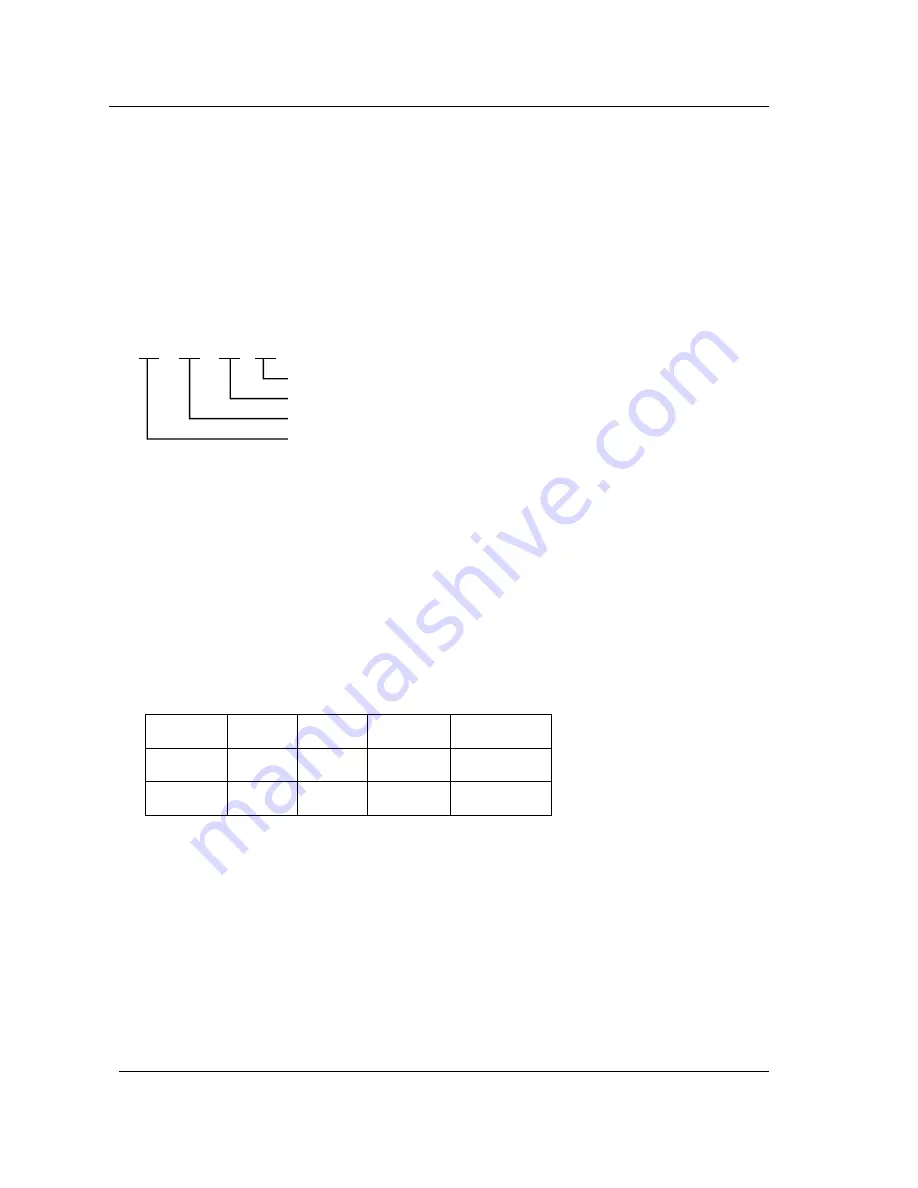
This lubrication method:

           1 -       A -       C -    Y

1.

 Positions need to be lubricated:

The positions need to be lubricated is indicated in numbers.

2.

 Lubricant type:

A: Shell Alvania Grease No. 2
B: Shell Terrace Oil 46

3.

 Amount of lubricant:

C: Coat thinly uniformly

4.

 Lubrication cycle:

 Y: Every year

Table 8.2 below shows the position to be lubricated.

Lubrication

Position

Lubricant

Type

Lubricant

Amount

Lubrication

Cycle

Lubrication

Position

1

B

C

Y

Sliding

rod

2

A

C

Y

Sliding

frame

Table 8.2

Positions need to be lubricated

(show in number)

Lubricant type

Amount of lubricant

Lubrication cycle

Содержание ScanCopier

Страница 1: ...ScanCopier Service Manual DOC 253 0038 0 Version 1 01 Avision Inc ...

Страница 2: ...YSTEM DIAGRAM 5 2 5 2 2 MAIN CONTROL CIRCUIT 5 3 5 2 3 SCSI INTERFACE 5 4 5 2 4 VIDEO CIRCUIT 5 4 5 2 5 SENSOR INPUT 5 5 5 2 6 SUB POWER SUPPLY CIRCUIT 5 6 5 2 7 POWER SUPPLY 5 6 6 TROUBLESHOOTING 6 1 6 1 TROUBLESHOOTING FLOWCHART 6 2 6 1 1 POWER ON TO SCANCOPIER READY 6 2 6 1 2 TROUBLESHOOTING FLOWCHART 6 3 6 2 TABLES 6 4 6 2 1 THE POWER LED DOES NOT LIGHT ON 6 5 6 2 2 THE POWER LED BLINKING CONT...

Страница 3: ...SASSEMBLY 8 5 8 3 2 DOCUMENT COVER 8 5 8 3 3 UPPER HOUSING 8 6 8 3 4 MAIN CONTROL BOARD ASSEMBLY 8 7 8 3 5 MOTOR BELT 8 8 8 3 6 OPTICAL CHASSIS 8 9 8 3 7 CCFL INVERTER PCBA 8 11 8 3 8 LAMP ASSEMBLY 8 12 8 3 9 MOTOR UNIT 8 13 8 3 10 LED PCBA 8 14 9 PARTS 9 1 9 1 SPARE PARTS LIST 9 1 ...

Страница 4: ...ake sure the power supply code of the ScanCopier is disconnected from the power outlet Under any circumstance do not remove from or install the PWBs or connectors onto the ScanCopier with the power supply turned ON 2 Use caution not to drop small parts or screws inside the unit when disassembling and reassembling If left inside they might cause the malfunction of the unit 3 Do not pull the connect...

Страница 5: ...nd light weight copier With only 3 7 kgs and a small foot print few inches more than an A4 page ScanCopier is easy and convenient to transport and relocate to fit your ever changing requirement 2 Ease of Use The control panel on the front of ScanCopier looks like a panel on a regular copier The operating steps follow the same procedure as other regular copier 3 Auto photo and text separation Incor...

Страница 6: ... to a 20 ppm laser printer Scanning Copying Size 8 5 x 14 Interface IEEE 1284 bi directional ECP EPP SPP Copy Feature Zooming From 25 400 Auto Zooming Auto Background Removal Auto Photo Text Separation Power Consumption 15 watts Photoelectric device Color CCD Light Source Cold Cathode Fluorescent Lamp Push Button Equipped LED 1 LED power Rated Voltage AC100 120V Frequency Range 50 60Hz Physical Di...

Страница 7: ...in a humid or dusty place Use care not to scratch the glass surface of the ScanCopier or the document holding pad with a clip or staple Do not use the wall socket with connecting devices which may generate noise for example air conditioner etc Use a suitable AC power source Place the ScanCopier on a level surface 3 2 UNPACKING PROCEDURE Unpack the ScanCopier according to the following procedure Re...

Страница 8: ...he following figure The lock switch is designed to protect the scanning head in case of any damage during shipment 1 2 Figure 3 2 Unlock the ScanCopier Note If you need to transport the ScanCopier be sure to first move the lock switch to the Lock position to prevent any damage during transportation 1 Lock Position 2 Unlock Position 1 Software CD 2 Power Adapter 3 One Parallel Cable 4 Quick Guide 5...

Страница 9: ...rinter See the Figure 3 3 Figure 3 3 Connecting to a laser printer 3 Connecting to Power a Plug the small end of the power cable supplied to the power jack on the back of your ScanCopier b Plug the large end of the power cable to the power outlet c Turn on your printer Printer Cable Copier Printer Power Cable Copier Power Jack To Printer port Figure 3 4 Connecting to Power ...

Страница 10: ...er and plug the other end into your PC where the printer port cable was plugging in Figure 3 5 ScanCopier cable connection 3 4 PLACING THE ORIGINAL 1 Place your original face down on the document glass 2 Observe that the upper left corner front page of your original is placed beneath the home position mark 1 2 3 Figure 3 4 Placing the original Document glass Document cover Your original Home posit...

Страница 11: ...Copier If the scanning head is located at a place other than the home position turn the ScanCopier on to return the scanning head to the home position Before making sure the scanning head is returned to the home position turn the power supply off 2 Move the lock switch to the lock position 3 Remove the power and printer cables 4 Put the ScanCopier in the packing case with the packing material ...

Страница 12: ...ScanCopier 4 1 4 PARTS IDENTIFICATION 4 1 External View 4 1 EXTERNAL VIEW 4 1 1 FRONT VIEW 1 Figure 4 1 Front view Document Cover Scanning Head Control Panel Document Glass Power on Light ...

Страница 13: ...nent used to scan the document on the document glass 4 Power on light Turns on when the ScanCopier is power on 4 1 2 REAR VIEW 1 Power jack Used to connect power cable 2 To PC Parallel port Used to connect parallel cable supplied 3 To Printer port Used to connect printer cable Power jack Figure 4 2 Rear view To PC Parallel port To Printer port ...

Страница 14: ... used 2 Feed direction The direction in which the scanning head moves 3 Scale The document glass provides some fixed sizes for example U S legal Letter A4 B5 A5 and A6 of a document on the glass 4 Hinge hole When installing the document cover or an optional unit insert the hinge into this hole Scale Hinge hole Home position Home position mark Control Panel Scanning head Feed Direction ...

Страница 15: ...0 P N 003 0099 0 INVERTER P N 104 0085 0 FCC CABLE P N 003 2021 0 SENSOR ASS Y P N 004 0168 0 PCBA UN02 FCC CABLE P N 104 0102 0 Motor Assy P N 002 0422 02 PCBA MB24 P N 004 0091 0 PCBA CB38 P N 004 0122 0 Lamp Assy P N 002 0424 0 Inverter P N 003 0099 0 FCC Cable P N 104 0085 0 Sensor Assy P N 003 2021 0 PCBA UNO2 P N 004 0168 0 FCC Cable P N 104 0102 0 ...

Страница 16: ...inal as shown in the above Figure 5 1 pass through the lens and creates an image on the CCD Charged Coupled Device Then according to the different light intensity perceived by the CCD the CCD will transfer these data into a series of analog signals to the main board where the signals are turned into digital signals These digital signals flows to the image processor to store into a printer acceptab...

Страница 17: ...M Figure 5 2 shows the system block diagram Figure 5 2 System block diagram 1284 Controller Video Circuit Main Board Control Section To Host Optical Unit Lamp Unit Inverter Power Adapter LCD Display Push Button 100 Vac 12Vdc To Printer Printer Host Computer ...

Страница 18: ...B external RAM work area 2 timer counters 4 I O ports 2 external interrupts and 2 internal interrupts for 2 internal timer counters Address Maps ROM program area Internal RAM working area External RAM working area 64KB Program 0000 FFFF 256 byte Internal Registers 00 FF System Memory 32KB ASIC Control Register 8KB 1284 Controller Image Processor 0000 7FFF 2000 2FFF 2800 28FF 2C00 0 2CFF ...

Страница 19: ... 2 VOR CCD Red Channel Output Signal 3 VOG CCD Green Channel Output Signal 4 VOB CCD Blue Channel Output Signal 5 A G Analog Ground 6 12Vc CCD Power Supply 7 12Vc CCD Power Supply 8 D G Digital Ground 9 RS CCD Reset Gate 10 CP Clamp Gate 11 PHI1 CCD Clock Phase 12 PHI2 CCD Clock Phase 13 SHR CCD Red Channel Shift Gate 14 SHG CCD Green Channel Shift Gate 15 SHB CCD Blue Channel Shift Gate 16 SH SHI...

Страница 20: ... processor includes all the necessary circuitry to perform three channel conditioning and sampling The signal chain consists of three channel correlated double sampling CDS and programmable gain adjustment of the CCD output PGA is a 10 bit analog to digital connector ADC quantizes the analog signal PGA Programmable gain amplifier ...

Страница 21: ...ss Data Bus bit 2 5 XAD3 80C32 Address Data Bus bit 3 6 D G Digital Ground 7 XAD4 80C32 Address Data Bus bit 4 8 XAD5 80C32 Address Data Bus bit 5 9 D G Digital Ground 10 XAD6 80C32 Address Data Bus bit 6 11 XAD7 80C32 Address Data Bus bit 7 12 VCC Digital Power Supply 13 VCC Digital Power Supply 14 T1 LCD Read Write Select Signal 15 D G Digital Ground 16 OCS5 LCD Chip Select Signal 17 RS LCD Regi...

Страница 22: ...s shown below 5V 5V Figure 5 3 Home position sensor The home position is detected when the carrier passes between the LED and the photo transistor 5 2 6 SUB POWER SUPPLY CIRCUIT The sub power supply circuit is provided for the internal analog circuit Input is 12V and output is Vcc and 5Va The circuit configuration is shown below 12Vdc Vcc 12Vdc 5Va The sub power supply is used for A D and logic ci...

Страница 23: ...lease see Table 5 1 for details Table 5 1 Power Adapter Type Characteristic Wall mount Input voltage range 200 240V Input current max 0 5A rms Input frequency 47 63Hz Max in rush current 115VAC cold start 30A Output voltage 12Vdc Min load current 0 0A Max load current 1 25A Total Power 15W ...

Страница 24: ...le modes relevant units and maintenance methods are described below When a problem occurs troubleshoot the problem according to the symptoms it shows Check the following first 1 Is anything operating improperly 2 Does the problem recur or is it regular Figure 6 1 to Figure 6 3 show the troubleshooting flowcharts The causes and maintenance methods for each failure mode are described in Table 6 1 th...

Страница 25: ...TROUBLESHOOTING FLOWCHART 6 1 1 POWER ON TO SCANCOPIER READY Figure 6 1 Power on to ScanCopier ready Power on LCD shows Warming up Message No Yes See Table 6 1 Wait for command from host LCD shows 1 Copy 100 Ready LED on ...

Страница 26: ...ng Check printer online Reading performed Printing completed Image not clear Noises generated END Copy button pressed No Yes Yes Yes Yes Yes No No Yes No No See Table 6 2 See Table 6 3 See Table 6 5 See Table 6 6 No See Table 6 4 Figure 6 2 Copier operation flowchart ...

Страница 27: ...ScanCopier 6 4 6 1 3 CONTORL PANEL OPERATION Copier online troubleshooting LCD shows message Value setting Wait for key pressing No Yes Yes END No See Table 6 7 Figure 6 3 Control panel operation ...

Страница 28: ...ion Table 6 1 The Ready LED does not light up or the LCD does not display Table 6 2 Printer does not react Table 6 3 Optical path dirty or hardware problem Table 6 4 Printer does not print Table 6 5 Image not clear Table 6 6 Noise generated Table 6 7 LCD does not show message after command ...

Страница 29: ...ntrol PCB or the LED board Tester check 12V GND Remove the cause or replace the PCB LCD module main board connection failure LCD module main board Visual check Plug the connector and secure it firmly 6 2 2 PRINTER DOES NOT REACT Table 6 2 Cause Relevant Unit Check Method Maintenance Method Printer cable failure Printer cable Visual check Secure printer cable firmly or replace the printer cable Mai...

Страница 30: ...ach the scanner cable Scanner link failure Main PCB Visual check Replace the PCB 6 2 4 PRINTER DOES NOT PRINT Table 6 4 Cause Relevant Unit Check Method Maintenance Method Printer does not has PCL language Printer Visual check Change PCL emulation printer Paper size incorrect Paper tray Visual check Replace paper tray Printer problem Visual check Check printer ...

Страница 31: ...toner or replace the toner Printer memory not enough Printer Visual check Add printer memory 6 2 6 NOISE GENERATED Table 6 6 Cause Relevant Unit Check Method Maintenance Method Motor unit failure Motor unit Replace the motor unit Replace the motor Main control PCB failure Main control PCB Replace the main control PCB Replace the main control PCB Scanning module failure Scanning module Check scanni...

Страница 32: ...D DOES NOT SHOW MESSAGE AFTER COMMAND Table 6 7 Cause Maintenance method LCD module cable failure Attach the LCD module cable and secure it firmly LCD problem Replace the LCD module Push button failure Replace the LCD module ...

Страница 33: ...t glass is contaminated with ink toner particles or paper coatings In this case the ScanCopier will have to be cleaned frequently to ensure the best performance Follow the cleaning procedure as below 1 Open the document cover 2 Dip a clean cloth with non corrosion solvent like alcohol purity above 99 5 3 Wipe the document cover and the document glass gently as shown in Figure 7 1 Continue until l ...

Страница 34: ...ScanCopier 7 2 1 Figure 7 1 Cleaning Document cover Document glass ...

Страница 35: ...r the maintenance of this equipment No Name Description 1 Minus screwdriver Idler pulley module screw 2 Philips screwdriver magnetic Nominal No 2 M3 M4 3 Oil Shell Terrace Oil 46 4 Grease Shell Alvania Grease No 2 5 Alcohol Isopropyl 91 Cleaning 6 Digital voltmeter With 0 01 V range 7 Oscilloscope 100 MHz or more with external sweep 8 Blower Cleaning Table 8 1 Maintenance tools ...

Страница 36: ...ted is indicated in numbers 2 Lubricant type A Shell Alvania Grease No 2 B Shell Terrace Oil 46 3 Amount of lubricant C Coat thinly uniformly 4 Lubrication cycle Y Every year Table 8 2 below shows the position to be lubricated Lubrication Position Lubricant Type Lubricant Amount Lubrication Cycle Lubrication Position 1 B C Y Sliding rod 2 A C Y Sliding frame Table 8 2 Positions need to be lubricat...

Страница 37: ...ScanCopier 8 3 SLIFING GUIDE SLIDING ROD Figure 8 1 Positions need to be lubricated 2 Sliding Rod 1 Sliding Guide ...

Страница 38: ...that must not be disassembled 4 Store the disassembled parts in a clean place to avoid loss 5 After replacement check the contacts and spare part mounting 6 Assemble the parts in reverse order of disassembly procedure 8 3 2 DOCUMENT COVER 1 As shown in the figure below lift the document cover to remove the studs from the hinge holes The studs are loosely attached to the hinge holes in the purpose ...

Страница 39: ...ment cover as described in the previous section 2 As shown in the figure below loosen the fixing screws with a Philips screwdriver 3 Remove the upper housing by lifting it gently Figure 8 3 Upper housing removal Fixing Screws Document Glass Upper Housing ...

Страница 40: ...fixing screws of the metal cover from the bottom housing as shown in the figure below 2 Loosen the fixing screws to remove the metal cover 3 Loosen the fixing screws of the SCSI connector with proper tool Figure 8 4 Main control PCBA removal Bottom housing 8 6 ...

Страница 41: ...l PCBA See section 8 3 4 and 8 3 4 2 Disconnect the motor belt by releasing the belt spring as shown in the figure below Note During the assembling process keep the belt straight in center line Figure 8 5 Belt removal Bottom housing Optical chassis Motor belt Sliding rod ...

Страница 42: ...ng rod and pull it out Figure 8 6 Optical chassis removal Attention Do not remove the flat cable from the optical chassis ASSEMBLING PROCEDURE Assemble the part in reverse order of the disassembling procedure Note Do not remove the flat cable from the optical chassis as the flat cable need special tool to reinstall it Any unauthorized action may cause unexpected result and will therefore not be re...

Страница 43: ...ScanCopier 8 9 Flat cable Optical chassis Figure 8 7 The correct direction of the CCD flat cable Flat cable Optical chassis ...

Страница 44: ...ove optical chassis See section 8 3 6 2 Remove the CCFC inverter PCBA from the optical chassis 3 Disconnect the CCFL inverter cable and CCFL inverter PCBA cable Figure 8 7 CCFC Inverter PCBA removal Optical chassis CCFL inverter CCFL inverter cable ...

Страница 45: ... Remove the CCFC inverter See section 8 3 7 2 Loosen the fixing screws of the lamp holder 3 Disconnect and replace the old lamp assembly with a new one 4 Fix the lamp assembly in place with the fixing screw Figure 8 8 Lamp assembly removal ...

Страница 46: ... chassis and the CCFL inverter PCBA See section 8 3 4 and 8 3 7 3 Remove the lamp assembly by loosing the fixing screws See section 8 3 8 4 Loosen the fixing screws as shown in the figure below 5 Remove the motor cable connector Figure 8 9 Motor unit removal Motor unit Motor cable Fixing Screws ...

Страница 47: ... Remove the upper housing See section 8 3 3 2 Remove the main control PCBA See section 8 3 4 and disconnect the LED cable 3 Loosen the fixing screw to remove the LED PCBA and replace a new one 4 Reassemble the upper housing and the main board LED PCBA Fixing screw ...

Страница 48: ... section 8 3 3 2 Remove the main control PCBA See section 8 3 4 and disconnect the LED cable 3 Loosen the fixing screw to remove the LED PCBA and replace a new one 4 Reassemble the upper housing and the main board Figure 8 10 LED PCBA removal LED PCBA Fixing screw ...

Страница 49: ...ScanCopier 9 1 9 PARTS 9 1 Spare Parts List 9 1 SPARE PARTS LIST 3 3 3 3 1 3 2 5 4 4 4 2 6 4 4 3 4 5 2 4 1 1 ...

Страница 50: ...ScanCopier Manual Driver Kit CD I _ I I D 9 2 ...

Страница 51: ...R MODULE 003 7256 0 1 6 BELT ASSEMBLY 003 7257 0 1 7 MAIN BOARD ASSEMBLY PCBA MB24 003 7258 0 1 8 CONTROL UNIT 003 7262 0 1 8 1 CONTROL COVER ASSEMBLY 003 7260 0 1 8 2 CONTROL BOARD ASSEMBLY 003 7261 0 1 9 IDER PULLY ASSEMBLY 03 7263 0 1 A DB25P CABLE 003 7046 0 1 B Power Adaptor B 1 Plug In Power Adaptor 12V 1 25A 15W 100 120V 003 7125 0 1 B 2 Plug In Power Adaptor 12V 1 25A EIAJ FULL RANGE 003 7...

Отзывы: