7
English
Connecting Cables
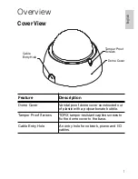
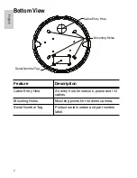
Refer to the diagrams in the Overview section for the location of the
different connectors.
To connect the cables required for proper operation, complete the
following:
1.
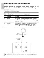
If there are external input or output devices that need to be
connected to the camera (for example: door contacts,
relays, etc), connect the devices to the camera I/O
Terminals.
For more information, see
Connecting to External Devices
.
2.
If an external microphone or external video monitor needs
to be connected to the camera, connect the devices to the
camera Audio/Video Connector.
For more information, see
Connecting to Microphones and
Video Monitors
.
3.
Connect the Ethernet Port (RJ45 connector) to a network
using an Ethernet network cable. The Link LED will turn on
once a network link has been established.
4.
Connect power using one of the following methods:
•
Power over Ethernet (PoE) Class 3 — If PoE is
available, the camera is automatically detected
when the network cable is connected.
•
External Power — Connect an external 12 VDC or
24 VAC power source to the power connector block.
For more information, see
Connecting Power
.
5.
Check that the Connection Status LED indicates the
correct state.
For more information, see
LED Indicators
.
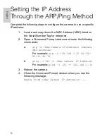
Assigning an IP Address
The camera automatically obtains an IP address by default. Once
connected to a network, it attempts to locate and obtain an IP address
from a DHCP server. If this fails, Zero Configuration Networking
Содержание 1.0-H3-D1
Страница 2: ......
Страница 8: ...English ...
Страница 28: ......
Страница 34: ...Français ...
Страница 54: ......
Страница 60: ...Español ...
Страница 80: ......
Страница 86: ...Italiano ...
Страница 106: ......
Страница 112: ...Deutsch ...
Страница 132: ......
Страница 138: ...Português ...
Страница 157: ...19 Português ...
Страница 158: ... 2 21 13 Avigilon Corporation ...


