Avid Technology CNC Rotary Axis Скачать руководство пользователя страница 12

1.1.1.8

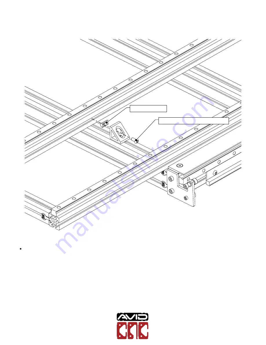
Attach the bracket to the rotary frame as indicated, partially tightening the fasteners.

M8 Roll-in T-Nut

M8 x 16mm Button Head Cap Screw

Avid CNC Rotary Axis
Table Top Installation &
Calibration Instructions


Version 2019Q4.2

© 2019

All Rights Reserved

Содержание CNC Rotary Axis

Страница 1: ...Avid CNC Rotary Axis Table Top Installation Calibration Instructions Version 2019Q4 2...

Страница 2: ...board for the rotary frame to sit in Use a pocket width of 355mm 14 and depth of 5mm 3 16 Position the rotary frame flush against one edge of the pocket An assembly video is available as a compliment...

Страница 3: ...ble Top Installation PRO CNC Machine Type Option For Benchtop installations skip to Section 1 2 Avid CNC Rotary Axis Table Top Installation Calibration Instructions Version 2019Q4 2 2019 All Rights Re...

Страница 4: ...et CRP195 00 PRO SHORT 2 M8 x 16mm Socket Head Cap Screw CRP195 00 PRO SHORT 1 M12 Proximity Sensor Cable 20 CRP190 00 BASE 1 NEMA 34 Motor Cable 20 Rotary Electronics 1 CRP195 00 FAST CRP195 00 PRO S...

Страница 5: ...ate to the tailstock end of the rotary frame as indicated M8 Roll in T Nut CRP831 01 Bumper Plate M8 x 16mm Socket Head Cap Screw 65mm 2 1 2 Avid CNC Rotary Axis Table Top Installation Calibration Ins...

Страница 6: ...anchor fasteners as indicated M8 Roll in T Nut 40 Series Anchor Fastener M8 x 30mm Socket Head Cap Screw Avid CNC Rotary Axis Table Top Installation Calibration Instructions Version 2019Q4 2 2019 All...

Страница 7: ...xtrusion to the back of the rotary assembly 4080 Extrusion 140mm 5 1 2 Assembly Note Center the extrusion on the rotary frame Avid CNC Rotary Axis Table Top Installation Calibration Instructions Versi...

Страница 8: ...icated M8 Roll in T Nut M8 x 16mm Socket Head Cap Screw CRP190 19 Mounting Bracket Assembly Note Position the bracket flush with the end of the 4080 extrusion Avid CNC Rotary Axis Table Top Installati...

Страница 9: ...machine table Assembly Note Locating the rotary assembly at the outer edges of the machine table will maximize routing work area Avid CNC Rotary Axis Table Top Installation Calibration Instructions V...

Страница 10: ...ounting bracket to the rear table crossmember as indicated M8 Roll in T Nut M8 x 16mm Socket Head Cap Screw Bottom View Avid CNC Rotary Axis Table Top Installation Calibration Instructions Version 201...

Страница 11: ...he front table crossmember partially tightening the fasteners M8 Roll in T Nut 4332 Mounting Bracket M8 x 16mm Button Head Cap Screw Avid CNC Rotary Axis Table Top Installation Calibration Instruction...

Страница 12: ...to the rotary frame as indicated partially tightening the fasteners M8 Roll in T Nut M8 x 16mm Button Head Cap Screw Avid CNC Rotary Axis Table Top Installation Calibration Instructions Version 2019Q4...

Страница 13: ...1 1 1 9 Use this process to install brackets at the four indicated locations 3 4 2 1 Avid CNC Rotary Axis Table Top Installation Calibration Instructions Version 2019Q4 2 2019 All Rights Reserved...

Страница 14: ...y Length Option This step is only applicable for rotary frame lengths 1850mm 72 and longer 7 8 6 5 Assembly Note These mid support brackets will not be tightened until the Mid Support Calibration sect...

Страница 15: ...the rotary frame until the measurements are within 1mm 1 32 of each other MEASURE MEASURE Assembly Note Final alignment of the rotary frame will occur in the Calibration Section Avid CNC Rotary Axis T...

Страница 16: ...1 1 1 12 Fully tighten the indicated mounting brackets Avid CNC Rotary Axis Table Top Installation Calibration Instructions Version 2019Q4 2 2019 All Rights Reserved...

Страница 17: ...2019 will use the X sensor port Motor Cable M12 Proximity Sensor Cable A Sensor Port A Motor Port Assembly Note For PRO machines purchased prior to 2019 an M12 splitter is required to connect the X an...

Страница 18: ...Installation Benchtop Machine Type Option To continue with PRO CNC installations skip to Section 1 3 Avid CNC Rotary Axis Table Top Installation Calibration Instructions Version 2019Q4 2 2019 All Rig...

Страница 19: ...t CRP195 00 BTP 2 M8 x 16mm Socket Head Cap Screw CRP195 00 BTP 1 M12 Proximity Sensor Cable 20 CRP190 00 BASE 1 NEMA 34 Motor Cable 20 Rotary Electronics 1 CRP195 00 FAST CRP195 00 BTP 2 40 Series An...

Страница 20: ...ate to the tailstock end of the rotary frame as indicated M8 Roll in T Nut CRP831 01 Bumper Plate M8 x 16mm Socket Head Cap Screw 65mm 2 1 2 Avid CNC Rotary Axis Table Top Installation Calibration Ins...

Страница 21: ...licable for Benchtop PRO installations M8 Roll in T Nut CRP190 19 Headstock Mounting Bracket M8 x 16mm Socket Head Cap Screw Bottom View Assembly Note Center the bracket on the rotary frame Avid CNC R...

Страница 22: ...ype Option This step is only applicable for Benchtop PRO installations M8 Roll in T Nut 40 Series Anchor Fastener M8 x 30mm Socket Head Cap Screw Avid CNC Rotary Axis Table Top Installation Calibratio...

Страница 23: ...fasteners Machine Type Option This step is only applicable for Benchtop PRO installations 4080 Extrusion 122mm 4 3 4 Assembly Note Use the upper t slot of the rear table crossmember Avid CNC Rotary A...

Страница 24: ...ated and fully tighten the fasteners Machine Type Option This step is only applicable for Benchtop PRO installations 137mm 5 3 8 Avid CNC Rotary Axis Table Top Installation Calibration Instructions Ve...

Страница 25: ...ary assembly on the machine table Assembly Note Some parts of the machine are hidden for illustrative purposes Avid CNC Rotary Axis Table Top Installation Calibration Instructions Version 2019Q4 2 201...

Страница 26: ...only applicable for Benchtop Standard installations 146mm 5 3 4 Assembly Note Measurement shown is from the back of the table crossmember to the back of the rotary frame Avid CNC Rotary Axis Table Top...

Страница 27: ...usion as indicated Machine Type Option This step is only applicable for Benchtop PRO installations M8 x 16mm Socket Head Cap Screw Bottom View Avid CNC Rotary Axis Table Top Installation Calibration I...

Страница 28: ...he front table crossmember partially tightening the fasteners M8 Roll in T Nut 4332 Mounting Bracket M8 x 16mm Button Head Cap Screw Avid CNC Rotary Axis Table Top Installation Calibration Instruction...

Страница 29: ...to the rotary frame as indicated partially tightening the fasteners M8 Roll in T Nut M8 x 16mm Button Head Cap Screw Avid CNC Rotary Axis Table Top Installation Calibration Instructions Version 2019Q4...

Страница 30: ...1 2 1 11 Use this process to install brackets at the four indicated locations 3 4 2 1 Avid CNC Rotary Axis Table Top Installation Calibration Instructions Version 2019Q4 2 2019 All Rights Reserved...

Страница 31: ...1 2 1 12 Fully tighten the indicated mounting brackets Avid CNC Rotary Axis Table Top Installation Calibration Instructions Version 2019Q4 2 2019 All Rights Reserved...

Страница 32: ...ed prior to October 2019 will use the X sensor port A Sensor Port A Motor Port Motor Cable M12 Proximity Sensor Cable Assembly Note An M12 splitter is required to connect the X and X limit switches to...

Страница 33: ...calibration procedure in this section will need to be completed each time the rotary assembly is installed on the CNC machine Avid CNC Rotary Axis Table Top Installation Calibration Instructions Vers...

Страница 34: ...1 ER20 8mm Collet 1 CRP195 00 FAST CRP195 00 PRO SHORT 1 M8 x 25mm Socket Head Cap Screw 1 M8 Hex Jam Nut Required Tools 6mm Ball End Allen Wrench 13mm Combination Wrench Auto Z and Corner Finding To...

Страница 35: ...d Corner Finding Touch Plate Follow the instructions below to configure Mach4 for use with your rotary axis Mach4 Usage Note If you have not previously installed and configured Mach4 for your CNC mach...

Страница 36: ...elect the appropriate length of your rotary axis Save these changes Mach4 Usage Note If you have already configured Mach4 with these rotary options you do not need to save any changes Avid CNC Rotary...

Страница 37: ...bled cutting method Mach4 Usage Note The Machine Setup Notes will list any motor sensor connections that may need to be changed when using rotary Avid CNC Rotary Axis Table Top Installation Calibratio...

Страница 38: ...your machine 1 3 2 1 Insert the M8 dowel pin into your spindle using the supplied 8mm ER20 collet Beveled end into spindle 8mm x 120mm Dowel Pin Assembly Note Ensure the beveled end is inserted in th...

Страница 39: ...tail stock at the front table crossmember as indicated Lock the tail stock in place using the spring plungers Avid CNC Rotary Axis Table Top Installation Calibration Instructions Version 2019Q4 2 2019...

Страница 40: ...plate on the touch plate isolator Position the bottom of the dowel pin roughly 25mm 1 above the center of the touch plate Avid CNC Rotary Axis Table Top Installation Calibration Instructions Version 2...

Страница 41: ...3 2 4 Ensure the magnet from the touch plate is attached to the dowel pin in the spindle Avid CNC Rotary Axis Table Top Installation Calibration Instructions Version 2019Q4 2 2019 All Rights Reserved...

Страница 42: ...Auto Z Touch Plate button Mach4 Usage Note You will need to Enable Mach4 to allow access to the Auto Z Touch Plate button Avid CNC Rotary Axis Table Top Installation Calibration Instructions Version 2...

Страница 43: ...2 6 There will now be a Rotary tab with rotary specific touch off and calibration functions Avid CNC Rotary Axis Table Top Installation Calibration Instructions Version 2019Q4 2 2019 All Rights Reser...

Страница 44: ...the Mounting Type and Orientation of your rotary assembly The Diagram buttons show the orientation for each Mounting Orientation option Avid CNC Rotary Axis Table Top Installation Calibration Instruc...

Страница 45: ...1 3 2 8 Enter the tool diameter of 8 and select mm for the units Avid CNC Rotary Axis Table Top Installation Calibration Instructions Version 2019Q4 2 2019 All Rights Reserved...

Страница 46: ...e Alignment button Mach4 Usage Note Use of the Rotary Touch Operations require your X Y and Z axes to be homed Avid CNC Rotary Axis Table Top Installation Calibration Instructions Version 2019Q4 2 201...

Страница 47: ...probe the first position Mach4 Usage Note The images and instructions shown in Mach4 will differ depending on your mounting type mounting orientation and rotary frame length Avid CNC Rotary Axis Table...

Страница 48: ...llow the instructions shown in Mach4 for Rotary Frame Alignment Step 2 to probe the second position Avid CNC Rotary Axis Table Top Installation Calibration Instructions Version 2019Q4 2 2019 All Right...

Страница 49: ...End Amount to raise the designated end of the rotary frame This will level the rotary frame in relation to your machine table Assembly Note The following steps will describe how to adjust the rotary...

Страница 50: ...cated corners loosen the bracket fasteners Assembly Note DO NOT loosen the fasteners at the fourth unmarked corner Avid CNC Rotary Axis Table Top Installation Calibration Instructions Version 2019Q4 2...

Страница 51: ...k bracket fasteners Machine Type Option This step is applicable only for PRO CNC and Benchtop PRO installations Bottom View Avid CNC Rotary Axis Table Top Installation Calibration Instructions Version...

Страница 52: ...Adjust the frame in the direction and amount that was shown on the screen in Mach4 Step 1 3 2 12 Avid CNC Rotary Axis Table Top Installation Calibration Instructions Version 2019Q4 2 2019 All Rights...

Страница 53: ...1 3 2 16 At the three indicated corners tighten the fasteners Avid CNC Rotary Axis Table Top Installation Calibration Instructions Version 2019Q4 2 2019 All Rights Reserved...

Страница 54: ...on the screen in Mach4 Assembly Note If shim stock is not available aluminum foil can be used Typical heavy duty aluminum foil is 0 024mm 0 001 thick Avid CNC Rotary Axis Table Top Installation Calib...

Страница 55: ...n the brackets attaching the rotary frame to the machine table Assembly Note Shimming at the tailstock end will follow the same procedure Avid CNC Rotary Axis Table Top Installation Calibration Instru...

Страница 56: ...ry frame and machine table crossmembers the appropriate amount Assembly Note Shim equally on each side of the rotary frame Avid CNC Rotary Axis Table Top Installation Calibration Instructions Version...

Страница 57: ...1 3 2 20 Tighten the bracket fasteners Avid CNC Rotary Axis Table Top Installation Calibration Instructions Version 2019Q4 2 2019 All Rights Reserved...

Страница 58: ...more than once to achieve proper alignment Rotary Length Option If your rotary frame is 1850mm 72 or longer continue to Section 1 3 3 If your rotary frame is 1550mm 61 or shorter click the Exit Frame...

Страница 59: ...on the tailstock at one of the mid support locations lock in place Position the spindle over the touch plate as indicated Avid CNC Rotary Axis Table Top Installation Calibration Instructions Version 2...

Страница 60: ...the instructions shown in Mach4 for Rotary Frame Alignment Step 5 to probe at the mid support location Avid CNC Rotary Axis Table Top Installation Calibration Instructions Version 2019Q4 2 2019 All R...

Страница 61: ...1 3 3 3 You will now see an amount to shim at the mid support location Avid CNC Rotary Axis Table Top Installation Calibration Instructions Version 2019Q4 2 2019 All Rights Reserved...

Страница 62: ...3 3 4 Shim the appropriate amount between the rotary frame and machine table crossmember Avid CNC Rotary Axis Table Top Installation Calibration Instructions Version 2019Q4 2 2019 All Rights Reserved...

Страница 63: ...1 3 3 5 Tighten the bracket fasteners Avid CNC Rotary Axis Table Top Installation Calibration Instructions Version 2019Q4 2 2019 All Rights Reserved...

Страница 64: ...routine If no more adjustments are required click the Exit Frame Alignment button Assembly Note Repeat the mid support procedure if you have mid support brackets at multiple locations Avid CNC Rotary...

Страница 65: ...headstock bracket to the machine table crossmember Machine Type Option This section is applicable only from PRO CNC and Benchtop PRO installations Bottom View Avid CNC Rotary Axis Table Top Installat...

Страница 66: ...the indicated fasteners hand tightening only M8 Hex Jam Nut M8 x 25mm Socket Head Cap Screw Bottom View Avid CNC Rotary Axis Table Top Installation Calibration Instructions Version 2019Q4 2 2019 All R...

Страница 67: ...1 3 4 3 Tighten an additional 1 8 turn Bottom View Avid CNC Rotary Axis Table Top Installation Calibration Instructions Version 2019Q4 2 2019 All Rights Reserved...

Страница 68: ...1 3 4 4 Fully tighten the remaining fasteners and jam nut Bottom View Avid CNC Rotary Axis Table Top Installation Calibration Instructions Version 2019Q4 2 2019 All Rights Reserved...

Страница 69: ...rotary fixture offsets This procedure will only need to be completed during initial assembly and installation Caution Before continuing it is highly recommended to fully read section 1 4 Touch Plate O...

Страница 70: ...1 CRP193 00 CRP190 00 BASE 1 M8 x 120mm Dowel Pin 1 ER20 8mm Collet 1 CRP193 01 Rotary Chuck Locating Pin Required Tools Auto Z and Corner Finding Touch Plate Mach4 CNC Controller Software from Avid...

Страница 71: ...Position the preinstalled busing at the end of the chuck locating pin as indicated CRP193 01 Chuck Locating Pin Avid CNC Rotary Axis Table Top Installation Calibration Instructions Version 2019Q4 2 2...

Страница 72: ...Pin into the chuck CRP193 01 Chuck Locating Pin Assembly Note The wire on the Chuck Locating Pin is not shown in all images Avid CNC Rotary Axis Table Top Installation Calibration Instructions Version...

Страница 73: ...1 4 1 3 With the flange of the bushing flush against the chuck jaws tighten the chuck Avid CNC Rotary Axis Table Top Installation Calibration Instructions Version 2019Q4 2 2019 All Rights Reserved...

Страница 74: ...1 4 1 4 Remove the tailstock live center Avid CNC Rotary Axis Table Top Installation Calibration Instructions Version 2019Q4 2 2019 All Rights Reserved...

Страница 75: ...ck as indicated and lock in place Ensure the magnet from the touch plate is attached to the dowel pin in the spindle Avid CNC Rotary Axis Table Top Installation Calibration Instructions Version 2019Q4...

Страница 76: ...1 4 1 6 Set the tool diameter to 8mm Click the Set Touch Plate Offset button Avid CNC Rotary Axis Table Top Installation Calibration Instructions Version 2019Q4 2 2019 All Rights Reserved...

Страница 77: ...w the instructions shown in Mach4 for Set Touch Plate Offset Step 1 to probe the touch plate location Avid CNC Rotary Axis Table Top Installation Calibration Instructions Version 2019Q4 2 2019 All Rig...

Страница 78: ...ront View Caution The probing routine will probe the top of the Chuck Locating Pin followed be each side Ensure there will be ample clearance between the collet nut and chuck jaws Avid CNC Rotary Axis...

Страница 79: ...he spindle Connect the magnet from the Chuck Locating Pin to the touch plate Caution Failure to attach the magnets as described can cause the machine to crash Avid CNC Rotary Axis Table Top Installati...

Страница 80: ...low the instructions shown in Mach4 for Set Touch Plate Offset Step 2 to probe the Chuck Locating Pin Avid CNC Rotary Axis Table Top Installation Calibration Instructions Version 2019Q4 2 2019 All Rig...

Страница 81: ...1 4 1 11 The touch plate is now ready to be used with your rotary assembly Avid CNC Rotary Axis Table Top Installation Calibration Instructions Version 2019Q4 2 2019 All Rights Reserved...

Отзывы: