background image

XR Series Installation and Technical Instructions

13

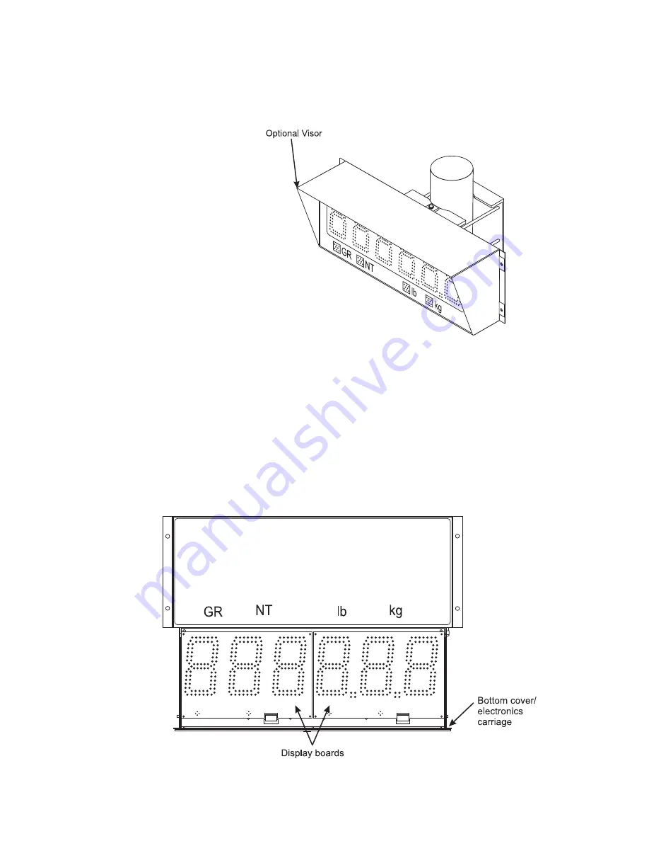
Visor Option

1.

Loosen the mounting hardware on the main enclosure 1/8th inch.

2.

Rest the visor’s mounting brackets on the bolt between the bolt head 
and the front of the side mounting plates.

3.

Re-tighten the mounting hardware.

Figure 2.4 Optional visor

Opening the Enclosure 
(Mounted)

1.

Make sure the unit is disconnected from power.

2.

Remove the captive screws from the bottom of the enclosure.

3.

Slowly, guide the electronics carriage out of the main enclosure, 
being careful to avoid bending any LED leads. Each LED is mounted 
very close to the PCB to prevent bending.

4.

The electronics carriage has tabs on either end that allow it to rest on 
the main enclosure’s flange when mounted (As seen in Figure 

2.5

 & 

2.6

).

Figure 2.5 Front view

Содержание XR 2000

Страница 1: ...XR Series LED Remote Displays XR LED Remote Displays Installation and Technical Instructions ENGLISH AWT35 000043 Issue AC May 21 2007 43121 0012 ...

Страница 2: ...XR Series_i_AWT35 000043 book ...

Страница 3: ...or trade with the public Declarations of compliance United States This equipment has been tested and found to comply with the limits for a Class A digital device pursuant to Part 15 of the FCC Rules These limits are designed to provide reasonable protection against harmful interference when the equipment is operated in a commercial environment This equipment generates uses and can radiate radio fr...

Страница 4: ...4 XR Series Installation and Technical Instructions ...

Страница 5: ...the XR 4500 4500TL or 6500 18 Power Wiring 18 Communications Wiring 19 Wiring the XR 2000 24 Power Wiring 24 Communication Wiring 25 Chapter 4 Wireless Communication 28 Wireless Set up for All XR Models 28 XR Remote Display 28 Indicator 28 Base Station Wireless Transceiver 29 Wireless Connection Test 31 Chapter 5 Start Up 32 Power Up 32 Reset Button 32 Auto Learn 32 LEARN Button 32 Diagnostic Indi...

Страница 6: ...grams 44 XR 4500 XR 4500TL and XR 6500 Utility Programs 44 Program 1 Normal Mode 44 Program 2 Axle Weighing with Totals 44 Program 3 Axle Weighing Driving On 44 Program 4 Command Mode 45 XR 2000 Utility Programs 47 Chapter 9 Troubleshooting Error Messages 49 Chapter 10 Spare Parts Lists 52 Chapter 11 Specifications 56 ...

Страница 7: ...s Manual Major sections of this manual are numbered and headed by titles in a black bar like Introduction above Subheadings appear in the left column Instructions and text appear on the right side of the page Occasionally notes tips and special instructions appear in the left column 1 2 Warnings Installation and configuration procedures as described in this manual should only be carried out by qua...

Страница 8: ...s Top XR 4500 Bottom XR 2000 The weight display is made up of 6 LED digits of 7 segments each Up to 2 decimal places can be displayed Five decimals on the XR 2000 The units have four annunciators under the display with bright LED markers GR Gross Weighing Mode NT Net Weighing Mode lb Pounds kg Kilograms ...

Страница 9: ...n should include Radio module External antenna Internal antenna cable Base station kit Opening an Unmounted Enclosure 1 When opening an XR unit 4500 4500TL 6500 prior to mounting place the unit top down on a smooth flat surface 2 Make sure the unit is disconnected from power 3 Remove the captive screws from the bottom of the enclosure 4 Angle the electronics carriage so the tabs are at opposite co...

Страница 10: ...tallation site for properly grounded power The electronics carriage may be removed to reduce weight when installing Mounting hole size in the case is 3 8 2 Ensure that mounting structures walls pole brackets etc will bear the weight of the display XR 4500 20 lbs XR 6500 4500TL 32 lbs 3 Allow proper clearance for lowering and removing the electronics carriage 4 Use proper hardware including wall an...

Страница 11: ...ole Mounting Bracket 1 Select appropriate height and fasten the small C bracket to the pole using the mounting clamps provided The pole mounting bracket allows use of poles or beams up to eight inches in diameter 2 Fasten the larger C bracket to the small C bracket using the hardware provided 3 Fasten the XR display to the pole mounting bracket as outlined in the mounting instructions See Figure 2...

Страница 12: ...12 XR Series Installation and Technical Instructions Installation Figure 2 3 Pole mounting bracket ...

Страница 13: ... Optional visor Opening the Enclosure Mounted 1 Make sure the unit is disconnected from power 2 Remove the captive screws from the bottom of the enclosure 3 Slowly guide the electronics carriage out of the main enclosure being careful to avoid bending any LED leads Each LED is mounted very close to the PCB to prevent bending 4 The electronics carriage has tabs on either end that allow it to rest o...

Страница 14: ...ure 2 6 Back view Lowering the Electronics Plate 1 Remove the two 2 captive screws holding the electronics plate to the electronics carriage 2 Slowly allow the electronics plate to swing down making access easier for wiring and service See Figure 2 7 Figure 2 7 Side view ...

Страница 15: ...red from the main enclosure disconnect the AC power and ground connections from the power supply board 2 Disconnect the green ground wire from the electronics carriage frame 3 Angle the electronics carriage so the tabs are at opposite corners of the main enclosure opening 4 Guide the electronics carriage free of the main enclosure ...

Страница 16: ...onnections See Figure 2 8 Figure 2 8 XR 2000 enclosure laid open Mounting Instructions 1 Inspect the installation site for properly grounded power Mounting hole size in the case is 5 16 2 Ensure that mounting structures walls posts etc will bear the weight of the display XR 2000 6 lbs 3 Use proper hardware including wall anchors where necessary when mounting the enclosure Secure the main enclosure...

Страница 17: ...XR Series Installation and Technical Instructions 17 2 2 Installing the XR 2000 Figure 2 9 XR 2000 dimensions ...

Страница 18: ...e standoff nuts and remove the terminal block from the mounting posts 3 Disconnect the factory supplied power cord from the terminal block and grounding post Do not remove the internal ground wire 4 Loosen the strain relief and pull the power cord through Run the new power cable through the strain relief Leave about 6 inches of wire to work with and tighten the strain relief 5 Connect the new grou...

Страница 19: ...ons wiring terminates at the controller board Communications should be wired before applying power to the unit if possible Communication Input Jumper A communications input type RS 232 RS 422 485 or 20 mA Loop must be selected by placing the jumper on the appropriate pins See photo and illustrations in Figure 3 2 Photo shows the input select jumpers circled in a thick white line Figure 3 2 Jumper ...

Страница 20: ...the indicator s communication wires at the RS 232 terminal J3 shown in Figure 3 3 Figure 3 3 RS 232 Terminal shown at arrow See the table below for pin assignments RS 232 Daisy Chain INDICATOR TO XR TRANSMIT TX RECEIVE RX RECEIVE RX NO CONNECTION SIGNAL GROUND GND SIGNAL GROUND SIG GND INDICATOR TO RD 1 TO RD 2 TX RX RX TX RX GND GND GND ...

Страница 21: ...mmunication Input Jumper JP 1 to RS485 2 Terminate the indicator s communication wires at the RS 485 terminal J4 shown in Figure 3 4 Figure 3 4 RS 422 485 Terminal See the table below for pin assignments INDICATOR TO XR TRANSMIT A TX A RECEIVE A RX A TRANSMIT B TX B RECEIVE B RX B ...

Страница 22: ...tor s communication wires at the RS 485 terminal J4 shown in Figure 3 4 using one of the following methods Parallel Multi drop wiring Split Multi Drop Wiring Multi Drop IDs are set using the CONFIG Dip switches For settings see Switches 8 9 Multi Drop ID on page 36 SCALE CONTROLLER TO RD 1 TO RD 2 TO RD 3 ETC TX A RX A RX A RX A RX A TX B RX B RX B RX B RX B ...

Страница 23: ...or pin assignments 20 mA Current Loop Mode Switch After the current loop is wired ACTIVE or PASSIVE mode must be selected SW 10 on the controller board Select Active mode if the XR is required to supply the current to the communicating device Select Passive mode if the communicating device indicator supplies the current to the XR If unsure of these requirements check the device s manual Figure 3 6...

Страница 24: ...d for power at the factory The factory supplied power cable can be removed for direct AC wiring if necessary HIGH VOLTAGE Only trained personnel should attempt the direct AC wiring procedure Ensure that the internal power cable is connected to the power supply board See Figure 3 7 Figure 3 7 XR 2000 power connection ...

Страница 25: ... Input Jumper A communications input type RS 232 RS 422 485 or 20 mA Loop must be selected by placing the jumper on the appropriate pins See Figure 3 8 Figure 3 8 Jumper positions RS 232 Wiring 1 Set the Communication Input Jumper JP 1 to RS232 2 Terminate the indicator s communication wires at the RS 232 terminal J3 See table below INDICATOR TO XR TRANSMIT TX RECEIVE RX RECEIVE RX NO CONNECTION S...

Страница 26: ...p Wiring Multi Drop IDs are set using the CONFIG Dip switches For settings see Switches 8 9 Multi Drop ID on page 36 20 mA Current Loop Wiring 1 Set the Communication Input Jumper JP 1 to 20mA LOOP 2 Terminate the indicator s communication wires at the 20 mA Current Loop terminal J5 See table below INDICATOR TO XR TRANSMIT A TX A RECEIVE A RX A TRANSMIT B TX B RECEIVE B RX B SCALE CONTROLLER TO RD...

Страница 27: ...nt loop is wired ACTIVE or PASSIVE mode must be selected SW 10 on the controller board Select Active mode if the XR is required to supply the current to the communicating device Select Passive mode if the communicating device indicator supplies the current to the XR If unsure of these requirements check the device s manual ...

Страница 28: ...eceive radio signals 4 If problems are experienced ensure that the radio module is seated properly on the PC board Check for bent pins Figure 4 1 Radio Module outlined in white on controller board Indicator 1 Connect the base station to the indicator or other communicating device as directed in the XStream Start Up Guide 2 Ensure the indicator is set up to output CONTINUOUSLY Note the indicator s ...

Страница 29: ...hown in Figure 4 2 The label on the unit identifies the various inputs and outputs of the base station Figure 4 2 Base station connects to the indicator Figure 4 3 shows the left end of the base station Figure 4 3 Base station view 1 Figure 4 4 shows the opposite end of the base station Figure 4 4 Base station view 2 ...

Страница 30: ... RS 232 DB 9 serial connector pin assignments 1 The base station s default communication settings are Baud Rate 9600 Data Bits 8 Parity None Stop Bits 1 If necessary adjust the base station s communication settings to match the indicator or other communicating device This requires a computer and XStream software package Refer to the XStream Start Up Guide for information 2 Power the base station u...

Страница 31: ...ructions 31 Wireless Connection Test Verify that both the base station wireless transceiver and the XR are set to the same radio channel If the XR s readings are incorrect erratic or very slow a different radio channel may need to be selected ...

Страница 32: ...he serial communications and string type The indicator s output string must contain number characters Also an STX character ASCII 02 must precede all other characters and or the string must end with CR character CR is ASCII 13 See example below STX Annunciator Weight Units CR Once Auto Learn is successful about 10 seconds after power up the XR will display the current weight 5 4 LEARN Button Autom...

Страница 33: ...rds STATUS Light The STATUS light blinks when power is applied to the unit Regular blinking once per second indicates that the XR has successfully learned a data string and is running properly Rapid blinking 3 times per second indicates that the XR is in Auto Learn mode attempting to interpret a data string COM Light The COM light flashes on each time the XR receives a character through any of its...

Страница 34: ...witch settings take effect only after the XR has been reset Cycle power directly or press the RESET button The XR 4500 4500TL and 6500 displays use two banks of dip switches on the controller board SW 3 SW 4 to set up the configuration and options These are shown in Figure 6 1 Figure 6 1 CONFIG and OPTIONS switches Configuration Options 6 ...

Страница 35: ...ically detects nighttime conditions and sets the display brightness to this level Lowering the brightness level at night helps reduce nighttime glare and energy costs Passing headlights spotlights etc will NOT activate the daytime brightness level Switch 5 Mirror Display Mode The XR s digits may be mirrored for applications where the display is viewed from a vehicle s rear view or side view mirror...

Страница 36: ...efore the XR will go into Auto Learn mode Switch 7 Reserved for Future Use Switches 8 9 Multi Drop ID If Multi Drop is not being used it is very important that Switches 8 9 be set in the OFF position Up to four 4 XR displays can share a serial or radio connection Messages are sent to individual displays using control codes and these Multi Drop IDs For Multi Drop instructions see Multi Drop address...

Страница 37: ...ght as applicable The XR will return to the selected brightness level when motion is detected on the scale Switch 6 Leading Zeros In some cases the scale indicator may transmit leading zeros in the output string If leading zeros are NOT required they may be suppressed The XR will automatically remove the leading zeros and replace them with blank spaces on the display Leading zeros may also be disa...

Страница 38: ...h installation must have its own radio channel selected If the wireless connection experiences interference problems from another radio site switching radio channels will most likely correct the problem The base station radio connected to the scale indicator must be configured with the same radio channel as the XR CHANNEL SWITCH 7 SWITCH 8 SWITCH 9 0 Default OFF OFF OFF 1 ON OFF OFF 2 OFF ON OFF 3...

Страница 39: ...g zeros in the output string If leading zeros are NOT required they may be suppressed The XR 2000 will automatically remove the leading zeros and replace them with blank spaces on the display Switch 3 Start up Auto Learn On power up the XR 2000 automatically enters Auto Learn mode analyzing the serial communications and string type In certain situations it may be necessary to disable this feature ...

Страница 40: ... channel selected If the wireless connection experiences interference problems from another radio site switching radio channels will most likely correct the problem The XR 2000 remote display must be configured with the same radio channel as the wireless transceiver connected to the indicator See Wireless Set up for All XR Models on page 28 Switches 8 9 Utility Program Select Please see the XR 200...

Страница 41: ...ernal traffic lights can be switched by the XR s built in relay 1 Wire the traffic light to the traffic light terminal J7 on the Controller board See Figure 7 1 Figure 7 1 Traffic light terminal See the pin assignments below Traffic Light Control 7 TRAFFIC LIGHT TO XR HOT COMMON RED NEUTRAL RED GREEN NEUTRAL GREEN ...

Страница 42: ...PEN An open contact is meant to correspond to a GREEN light 3 The XR controls the traffic light using the pre installed utility programs or serial commands in Command Mode only Pre installed Utility Programs The following utility programs control the built in relay for switching an external traffic light For program overviews see XR Utility Programs on page 44 Serial Commands When the XR is set in...

Страница 43: ...mote switches will be disabled if the XR has a program selected 2 The default condition switch contact open is GREEN When the switch contact is closed the light turns RED Pre installed Utility Programs The following utility programs control the built in traffic light For program overviews see XR Utility Programs on page 44 Serial Commands When the XR is set in Command Mode it will accept serial co...

Страница 44: ...is displayed for 10 seconds flashing Scale at or near ZERO GREEN light Ready for the next truck Program 3 Axle Weighing Driving On Use this for axle weighing on regular vehicle scales Scale at zero GREEN light Truck drives its first axle on the scale after motion stops RED light The XR displays and axle number A1 then the axle weight GREEN light The next axle is driven onto the scale After motion ...

Страница 45: ...owed by a CR character Example To display 1000 transmit 1000 CR Transmit Status Characters Status characters may be imbedded anywhere in the weight string to control the annunciator lights Status characters may be upper or lowercase and in any order before or after the weight Example To display 1000 lb gross transmit 1000LG CR or GL1000 CR Control Commands Control commands are single ASCII charact...

Страница 46: ...ress 0 to 3 is set using SW8 and SW9 on the CONFIG dipswitch bank See Switches 8 9 Multi Drop ID on page 36 When using Multi drop the XR will only respond after it has been selected To select the display transmit a character ASCII 35 followed by the correct ID number and a CR ASCII 13 character The XR will remain selected until it receives a command containing a different address Examples 1 Select...

Страница 47: ...t be created on the scale indicator that sends the scale weight and a CR character to the XR 2000 display with a button press Example 123456 lb g CR When the XR 2000 receives this information it displays the weight and keeps displaying it until another weigh ticket is received PROGRAM 3 RESERVED FOR FUTURE USE PROGRAM 4 COMMAND MODE All XR displays can be setup to receive commands directly from th...

Страница 48: ... Command Mode The Multi drop address 0 to 3 is set using SW8 and SW9 on the CONFIG dipswitch bank See Switches 4 5 Multi Drop ID on page 40 When using Multi drop the XR will only respond after it has been selected To select the display transmit a character ASCII 35 followed by the correct ID number and a CR ASCII 13 character The XR will remain selected until it receives a command containing a dif...

Страница 49: ...properly set Display reads Error 1 Verify the correct terminal RS 232 422 485 20 mA is being used and check wiring Verify that the communications Input Select jumper is properly set Verify that data is being sent to the XR from the indicator and that the data string contains numeric characters Baud Rate Auto Learn has failed Display reads Error 2 Verify the correct terminal RS 232 422 485 20 mA is...

Страница 50: ...Link radio connected to the scale indicator COM light not flashing Verify the correct terminal RS 232 422 485 20 mA is being used and check communications wiring at the indicator Verify that the communications Input Select jumper is set to the proper communication mode RS 232 422 485 20 mA If the radio module is being used also see Probable Solutions for Radio light not flashing Verify that data i...

Страница 51: ...XR Series Installation and Technical Instructions 51 ...

Страница 52: ...SCRIPTION 4016 XR 2000 REMOTE DISPLAY COMPLETE ASSY 4024 DISPLAY BOARD 4032 CONTROLLER BOARD 4040 POWER SUPPLY BOARD 4057 NON GLARE LENS 4065 ENCLOSURE BASE 4073 ENCLOSURE LID W GASKET 4081 POWER SUPPLY TO CONTROLLER BOARD CABLE 4099 5 RIBBON CABLE 4107 EXTERNAL POWER CORD 4115 2 GROUND WIRE 0022 GORTEX BREATHER VENT 0113 INTEGRATED WIRELESS RADIO MODULE WITH ANTENNA 0121 BASE STATION WIRELESS RAD...

Страница 53: ...SENSOR WINDOW 0063 20 RIBBON CABLE 0071 9 GROUND WIRE 0089 11 GROUND WIRE 0097 POWER SUPPLY TO CONTROLLER BOARD CABLE 0105 EXTERNAL POWER CORD 0113 INTEGRATED WIRELESS RADIO MODULE WITH ANTENNA 0121 BASE STATION WIRELESS RADIO MODULE WITH CABLE FOR INDICATOR 1012 XR 4500 REMOTE DISPLAY COMPLETE ASSY 1020 DISPLAY DIGIT PC BD 1038 ENCLOSURE 1046 BOTTOM COVER 1053 SUPPORT PLATE 1061 NON GLARE LENS 10...

Страница 54: ...0063 20 RIBBON CABLE 0071 9 GROUND WIRE 0089 11 GROUND WIRE 0097 POWER SUPPLY TO CONTROLLER BOARD CABLE 0105 EXTERNAL POWER CORD 0113 INTEGRATED WIRELESS RADIO MODULE WITH ANTENNA 0121 BASE STATION WIRELESS RADIO MODULE WITH CABLE FOR INDICATOR 3018 XR 4500 TL REMOTE DISPLAY COMPLETE ASSY 3026 DISPLAY DIGIT WITH SIGNAL LIGHT 3034 DISPLAY DIGIT PC BD 2036 ENCLOSURE 2044 BOTTOM COVER 2051 SUPPORT PL...

Страница 55: ...BON CABLE 0063 20 RIBBON CABLE 0071 9 GROUND WIRE 0089 11 GROUND WIRE 0097 POWER SUPPLY TO CONTROLLER BOARD CABLE 0105 EXTERNAL POWER CORD 0113 INTEGRATED WIRELESS RADIO MODULE WITH ANTENNA 0121 BASE STATION WIRELESS RADIO MODULE WITH CABLE FOR INDICATOR 2010 XR 6500 REMOTE DISPLAY COMPLETE ASSY 2028 DISPLAY DIGIT PC BD 2036 ENCLOSURE 2044 BOTTOM COVER 2051 SUPPORT PLATE 2069 NON GLARE LENS 2077 V...

Страница 56: ...999 to 999999 Input Data Interface RS 232 RS 485 20 mA Current Loop active or passive wireless RF Data Format Baud Rates 300 to 19 200 Auto learning or selectable 7 or 8 data bits even odd or no parity 1 or 2 stop bits Auto learning or selectable Output Interface Echo out port RS 232 Update Continuous or demand selectable Operating Environment 40 F to 120 F 40 C to 50 C 0 to 100 humidity nonconden...

Страница 57: ......

Страница 58: ...1 USA Tel 507 238 4461 Fax 507 238 4195 Email industrial weigh tronix com www wtxweb com Avery Weigh Tronix UK Foundry Lane Smethwick West Midlands England B66 2LP Tel 44 0 870 903 4343 Fax 44 0 121 224 8183 Email info awtxglobal com www averyweigh tronix com ...

Отзывы: