Avery Dennison AP 2.4 Скачать руководство пользователя страница 29

2. Fonts, Bar Codes and Graphics Specification 

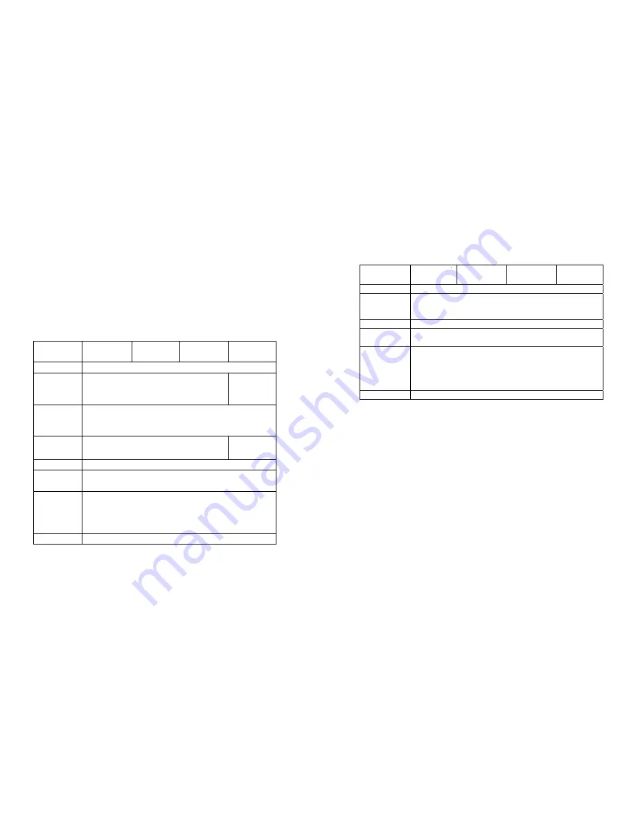
Printer Programming Language B, PPLB 


Specification


Model 

OS-202DT

Model

OS-204DT

Model

AP 2.4

Model 

OS-314TT


General fonts 5 fonts with different point sizes


Symbol sets 
(Code pages)

8 bits: code page 437, 850, 852, 860, 863 and 865. 7 
bits: USA, British, German, French, Danish, Italian, 
Spanish, Swedish and Swiss.


Soft fonts


Downloadable soft fonts


Font 
expandability

 
1x1 to 24x24


Bar code 
types


Code 39(checksum), Code 93, Code 128/ subset A,B,C, 
Codabar, Interleave 2 of 5(checksum), Matrix 25, UPC 
A/E 2 and 5 add-on, EAN-8/13, Code 128UCC, 
UCC/EAN, Postnet, German Postcode. MaxiCode and 
PDF417 (2D symbologies)


Graphics


PCX and binary raster


The specifications of fonts, bar codes and graphics depend on the 
printer 

interpreter

. The emulation is a printer programming 

language, through which the host can communicate with your 
printer. There are two printer programming languages for models 
202/204/214/314, they are PPLAand PPLB. 


Printer Programming Language A, PPLA 

Specification


Model 

OS-202DT


Model


OS-204DT


Model


AP 2.4

Model


OS-314TT

General fonts


7 alpha-numeric fonts, OCR A and OCR B ASD


Smooth fonts


6, 8, 10, 12, 14 and18 points


4, 6, 8, 10, 

12, 14 and 18 

points


Symbol sets 

for fonts 

smooth


USASCII, UK, German, French, Italian, Spanish, 

Swedish, and Danish/Norwegian


Courier fonts


8 symbol set (PC, PC-A,PC-B EAMA-94, 
Roman8, Legal,

 Greek and Russian)


Soft fonts


Downloadable PCL fonts


Font 

expandability


1x1 to 24x24


Bar code 

types


Code 39, Code 93, Code 128/subset A,B,C,    Codabar, 

Interleave 2 of 5, UPC A/E/2 and 5 add-on, EAN-8/13, 

UCC/EAN-128, Postnet, Plessey, HBIC, Telepen and 

FIM. MaxiCode and PDF417 (2D symbologies).


Graphics


PCX, BMP, IMG and HEX formats


Notes : 

1. The bare core for ribbon must be 11 cm in length. It should 

have two opposite slits at two ends. If the ribbon itself is 
less than 11 cm, it has to be aligned with the bare core at 
left end when you install it. 

2. Since this printer uses band buffer technology, if you just 

print texts or barcodes the maximum length can be more 
than 30 inches, whereas if you print many graphics the 
maximum length can only be few inches under standard 
onboard RAM.(The extension RAM, font board and flash 
modules use the same connector, they cannot function at 
the same time.) 


53


54

Содержание AP 2.4

Страница 1: ...evices Shielded cables must be used with the unit to insure compliance The user is cautioned that any changes or modifications not expressly approved by Avery Dennison could void the user s authority...

Страница 2: ...ls 25 Performing Calibration 27 Printing Configuration Report 27 Resetting the Printer 28 Hooking up the Printer and the Computer 29 Communicate with the Printer 32 Troubleshooting 44 Caring for Your...

Страница 3: ...r to see if the media compartments are in order If damages did occur immediately file the claim to the shipping company for settlement Having performed the primary inspections next step please check w...

Страница 4: ...into an appropriate AC electrical outlet WARNING NEVER OPERATE THE PRINTER AND POWER SUPPLY IN AN AREA WHERE THEY CAN GET WET 3 When plugging the connector into power jack please leave the power switc...

Страница 5: ...Ribbon Pick up Holder Release Levers Media Hanger Top Cover H Cover Power Indicator Ready Indicator Feed Button 6 Thermal Printhead Platen Roller Power Switch Peel Off Option White Plastic Roller Cutt...

Страница 6: ...eatures AP 2 4 Top Cover Thermal Printhead Power Switch H Cover Power Indicator Ready indicator Feed Button Release Levers Platen Roller Media Hanger 8 Peel Off Option Cutter Option White Plastic Roll...

Страница 7: ...ting 1 Lift the top cover to expose the media compartment 2 Unlatch the print head module by pushing the two white release levers on the sides toward the rear 3 Turn over the print head module to expo...

Страница 8: ...into the pick up holder first snap in the left side then the right side 5 Attach the edge of the ribbon on the bare core and wind it a little bit onto the core 6 Insert the ribbon roll into the supply...

Страница 9: ...ons standard peel off or with a cutter Standard mode allows you to collect each label freely In peel off mode the backing material is being peeled away from the label as it is printed After the former...

Страница 10: ...the media compartment 3 Load the media roll onto the hanger from the left 5 Move the media roll to the left end 6 Move the shield to the left next to the media Media Compartment Media Hanger Media Co...

Страница 11: ...head module upright with one hand to allow the media pass under it Lead the media through the media guides with the other hand 11 Close the top cover and turn on the printer or press the feed button i...

Страница 12: ...nser bar and H cover ensuring that it is inserted between white plastic roller and platen roller Installing the dispenser kit please refer to the Appendix I Follow the common procedure of Loading the...

Страница 13: ...eel Off mode powered on status in case of improper installation just keep pressing the FEED button to back feed the label stock to re install it Note 14 To remove any slack just rewind the media onto...

Страница 14: ...Follow the same procedure as Loading the Media from Note step 1 to step 8 The FEED button will not drive the printer to cut The cutting work can be executed only when the software 9 Thread the media...

Страница 15: ...ondition Press back feed the label to correct label installation in case that label is not properly installed for OS 202 Peel Off mode only Keep pressing while turning on the power to print out a conf...

Страница 16: ...st always be carried length and come back to the factory default settings out whenever media is being changed Failure to do so will result in miss detection of the label sensor Note All settings are s...

Страница 17: ...plies with FCC Rules and Regulations Part 15 for Class B Equipment using fully shielded six foot data cables Use of longer cables or unshielded cables may increase radiated emissions above the Class B...

Страница 18: ...ong as they are for Windows Before installation 1 Check the contents of the driver to ensure it is complete Data cables must be of fully shielded construction and fitted with metal or metalized connec...

Страница 19: ...river path ArgoBar File New Select Printer Label Dr on LPT1 OK 5 Click Browse button 6 Select the proper directory for installation LabelView WIN95 File Select Printer Label Dr on LPT1 OK WIN98 WIN200...

Страница 20: ...rding to the print direction Paper source Media type T T stands for thermal transfer ribbon mode and D T for direct thermal mode without ribbon Media choice Darkness Set the heat value or darkness fro...

Страница 21: ...click more option select Enable without cutter peeler click OK Print quality Speed Properties menu click Device Options select parameters click OK 38 Create a new size Properties menu click Paper sel...

Страница 22: ...Printing Reference click Paper Quality select media type click OK 40 Orientation Printing Reference menu click Layout select Portrait or Landscape click OK Paper size Copies Media choice Accessory set...

Страница 23: ...enter a form name for the new form in Form description for reset the paper size in the specific squares of the Measurements click OK Paper size Orientation Paper source Media type Copies Media choice...

Страница 24: ...tem to select desired A Power and Ready LEDs blink at the same tempo parameter click OK Power LED Ready LED ON ON OFF OFF Create a new size Please refer to the procedure of create a new size on Win 20...

Страница 25: ...nated check the fuse inside the power adapter case The data has been sent but there is no output from the printer Check the active printer driver if Label Dr for your Windows system and the label prin...

Страница 26: ...ontinue your print jobs after the abnormal conditions have been corrected simply press the panel button or restart the printer Make sure that the LED is not blinking and remember to resend your files...

Страница 27: ...sh the print head firmly into the casing and shift it to the left It will release from the module 5 Disconnect the print head cable 6 Dissemble the print head and the mounting bracket by releasing scr...

Страница 28: ...ll above media plus thermal transfer paper or vinyl labels and tags butt cut or die cut with various adhesives Maximum label roll diameter 4 3 in 109mm outside diameter 1 in 25 mm inside diameter Labe...

Страница 29: ...Model OS 204DT Model AP 2 4 Model OS 314TT General fonts 7 alpha numeric fonts OCR A and OCR B ASD Smooth fonts 6 8 10 12 14 and18 points 4 6 8 10 12 14 and 18 points Symbol sets for fonts smooth USAS...

Страница 30: ...6 Out DTR 7 Out RTS 8 In CTS 9 Out 5V Host 25S Printer 9P Host 9S Printer 9P PC or compatible PC or compatible DTR 20 1 DSR DTR 4 1 DSR DSR 6 6 DTR DSR 6 6 DTR TX 2 2 RX TX 3 2 RX RX 3 3 TX RX 2 3 TX...

Страница 31: ...and you use Xon Xoff as flow control it will be problem free Baud rate 2400 4800 9600 19200 and 38400 programmable by command Data format always 8 data bits 1 start bit and 1 stop bit Parity always n...

Страница 32: ...m SO RS N n SI US O _ o DEL 2 Unwrap the PC bag of dispenser kit to take out the screw the shaft the plastic roller the dispenser bar the direction label and the peeler sensor cable Top Cover 3 Take o...

Страница 33: ...nsor cable and sensor board with Loctite 444 instant adhesive or equivalent 8 Release the two screws at the bottom of the base housing 9 Remove the middle cover 10 Take off the H Cover Sensor Cable 11...

Страница 34: ...he sensor cable connector through the hole on the upper left corner of middle cover Dispenser Bar Screw Bracket Screw White Plastic Roller 13 Unlatch the print head module Hook the white roller on the...

Страница 35: ...oard of the base housing 1 Turn off the printer power unplug the power cable and Centronics Serial cable 21 Click the middle cover back to the base housing First click in the front part then the rear...

Страница 36: ...rd 6 Secure four attached screws for the cutter Print Head Assembly 68 Cutter 7 Plug the cutter s connector into the PCB s header connector JP13 8 Reinstate the print head assembly by securing back th...

Отзывы: