


Revision
:
0
Manufacturing Section:P
E
Date
:
2005.04.18
Difference
Operating Item
Part name / Specification
Parts Number
Q'TY
Operation Description
Important Note
Jig /Fixture
1
F10DA1-HINGE-L-D3049
40-015141-01
1
NA
2
F10DA1-COVER FOR LCD HINGE-L-#8160-
D3047
50-035295-00
1
NA
3
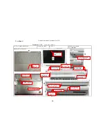
F10DA1-MYLAR FOR HINGE-L-F4250
50-023633-00
1
Attach the Mylar of left spindle on the spindle as the
position shown in the figure.
The mylar should be attached
squarely without slanting and
floating.
NA
5
NA
NA
1
Connect the LCD harness to the left and right connection
ports of the Inverter and then arrange the LCD harness and
Bluetooth wires as per the figure.
The wire must be arranged
from the gap above the
Inverter.
NA
6
Acetic tape (approx. 3cm long)
NA
2
Attach two pieces of acetic tape to fix the left and right
side of LCD harness, as per the figure.
Keep the wires from
lifting.
NA
Align the small hole on the
left side of spindle with the
positioning pole in the
Hinge Cover.
41-720526-03
Electrical Screwdriver/Torque:
2.5±0.2Kgf-cm
2
Lock two screws to fix the left spindle of LCD, as per the
figure.
Check if the angle of left
side of the spindle is 90
degrees.
PAGE
:
08
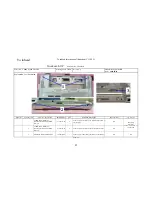
Explanation for illustration
Twinhead S.O.P
Document NO:TESOP586
Name of SOP:F10DA 10.6" LCD MODULE ASS'Y SOP
Working name
:
6512-7
Check the appearance of left spindle and left spindle
cover and then assemble the cover and the spindle as per
the figure.
4
SCREW ISOT-M2.6X3L-SELF-LOCKING-
B3516Z
T
w
inhead International (Kunshan) CO.,LTD
T
w
inhead
4
2
1
3
6
5
SAMSUNG LCD wire trimming
Make sure this part be 90 degrees
before locknig the screw in place.
When it becomes vertical, lock the
screw tightly.
51