WWW.AVENTURACCTV.COM
VERSION V1.02
Quick Start Guide
Related Series Models:
DHN-32P, DHN-64P
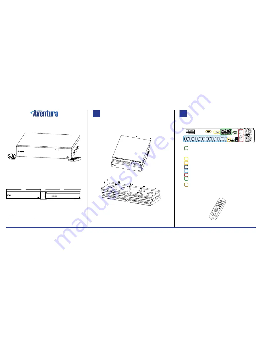
The product comes with the following components:
1. NVR Recording Device
2. USB Mouse
3. IR Remote Control
4. Power Adaptor 48V (not shown)
5. HDD Screw Pack
6. Quickstart Guide (this document)
Be sure no parts are missing from the product before installation.
PRODUCT DIMENSIONS
Information in this document is subject to change without notice. As our products are subject to continuous improvement,
Manufacturer reserves the right to modify product design, specifications without notice and without incurring any
obligation. E&OE
©2017 Aventura Technologies, Inc. All rights reserved.
AVENTURA TECHNOLOGIES, INC.
HEADQUARTERS
48 Mall Drive, Commack, New York 11725 U.S.A.
Tel: +1.631.300.4000 Fax: +1.631.434.7000
HDD INSTALLATION
Some units will come pre-fitted with an HDD, so this step would not be required. Proceed to
Step 2.
1. Remove the cover by unscrewing the screws located on the rear of the case.
The lid will slide back and lift off from the base part.
2. Inside the case is the HDD mounting. Detach unit, and fit up to 8HDDs as shown in the
diagram.
3.
Attach drive(s), so the connections face to the middle of the unit, attach to plate as
shown in the diagram, be sure that you install all screws, as HDDs are situated screw
side up.
4. Re-attach the units cover after connecting power and data cables located inside.
Note: Be sure to use all anti-static precautions and that the device is not turned on or any power is to any
device. We recommend both drives to be equal size make / manufacturer get best results.
CONNECTIONS
1. Connections to the device(s) labeled at the rear of the unit*; you should connect all
cables before you connect the power which you would normally connect last.
2. Connect Video outputs to your desired display devices(s), the 1080p requires an HDMI
cable, and VGA is standard 15Pin VGA style.
NOTE: Both display outputs can function at the same time, the resolution of VGA/HDMI output is changed
inside the device OSD settings.
3. RCA Connector for external audio input, and external audio output.
4. Connect RJ-45 network to your LAN or Router for remote access.
5. 1 x USB 3.0 ports back up. And two USB 2ports (one port at the device front)
6. PoE network camera ports, connect each of your PoE network devices to each port.
7. Connect external two IEC power inputs to the supplied Y-Cable.
8. Alarm inputs and alarm output. Single common ground for each input is used. Notice
that the 16Channel device has no external alarm input or outputs.
9. e-SATA, for external HDD for backup. Please connect before powering on the unit.
NOTE: To ensure no damage to the device, make all connections before you turn on the power switch.
REMOTE CONTROL
The supplied IR can be used to control menu of the device to duplicate mouse functions.
Note: Be sure to check remote batteries if left for a long period of time, and change cells when required.
[3.5 ]"
89mm
440mm
[17.3"]
460mm
[ 18.1"]
1
2
○
1
○
2
○
3


