


Installation
Installing the Control Unit
2-13
Initializing the System
2
5.
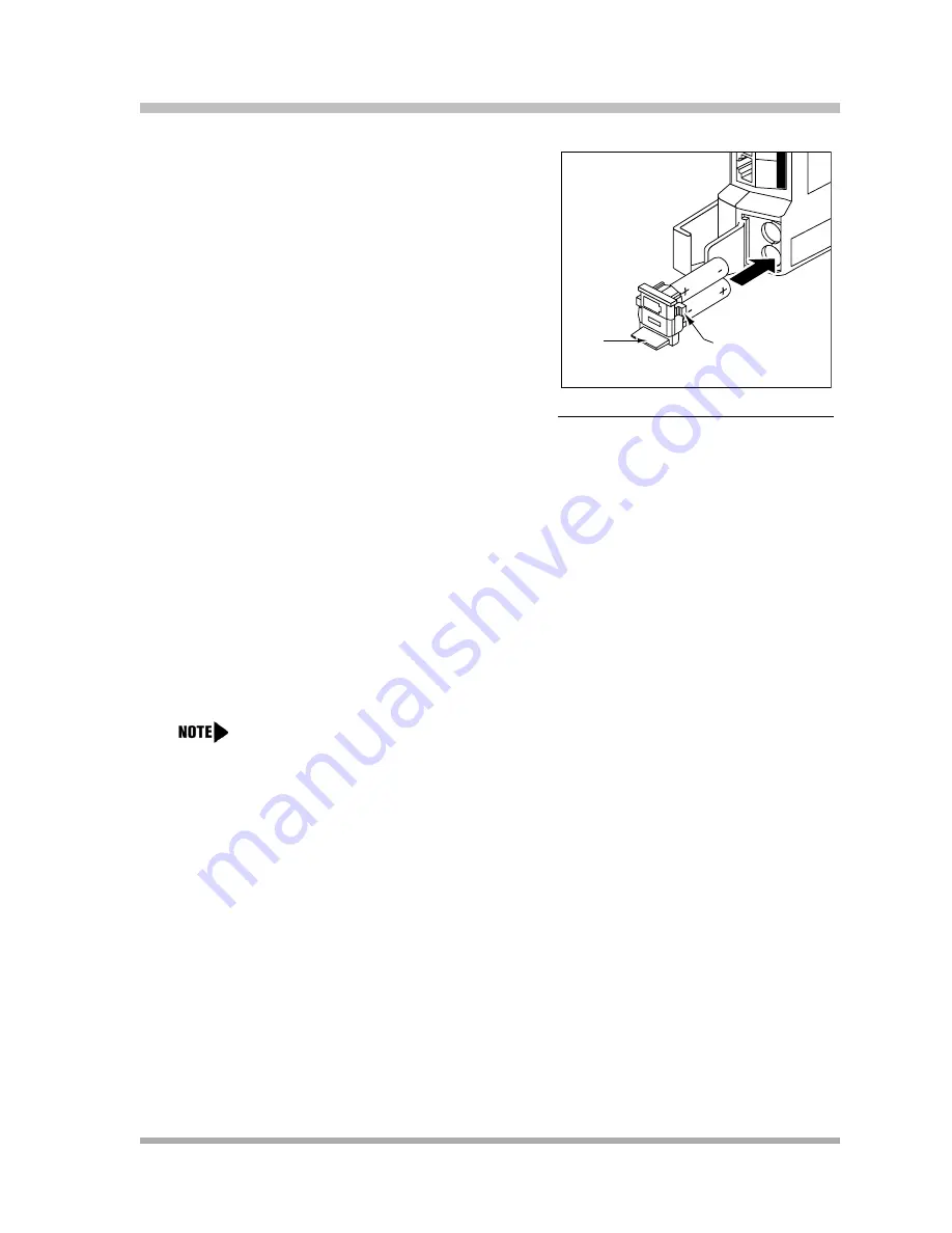
With the locking latch in the unlocked position
(battery icon and “minus” icon visible), slide the
battery assembly into the processor module
along the battery guides on the inside of the
battery compartment (see
). Push
the battery assembly in far enough that the
edges of the assembly slip behind the plastic
housing of the processor module.
Figure 2-15. Sliding the Battery
Assembly into the
Processor Module
6.
Pressing lightly on the battery icon on the front of the battery assembly, slide the locking
latch downward to secure the assembly in place. The “plus” icon and the battery icon should
now be visible on the front of the battery assembly (see
).
To initialize the system, you MUST insert the enclosed PC Card before powering up the
system for the first time. You may also insert any one of the additional supported PC Cards:
Backup/Restore card, Automatic System Answer/Direct Extension Dial (ASA/DXD) card,
PARTNER Voice Messaging Basics card, and PARTNER Remote Access PC Card (Release
3.0 and later systems).
Follow these steps to initialize a system:
1.
If your PC Card comes with a write-protect tab, verify that the write-protect tab on the PC
Card is not in the write-protected position. If it is, use a paperclip or another pointed object
to push the write-protect tab on the end of the PC Card upward to the nonprotected
position.
2.
To insert the PC Card, hold it with the label facing to the right, and slide it gently into one of
the PC Card slots on the processor module. When inserted properly, the PC Card projects
about 1-5/8” (4 cm) from the module.
3.
If you have a 5-slot carrier, make sure the carrier’s On/Off switch is at the Off (“O”) position.
Tab
Locking Latch
You must power down the system before you insert or remove a PC Card.
Содержание programming and use
Страница 10: ...PARTNER Advanced Communications System Installation Programming and Use viii Master TOC...
Страница 12: ...PARTNER Advanced Communications System Installation Programming and Use 1 ii...
Страница 30: ...PARTNER Advanced Communications System Installation Programming and Use System Components 1 18...
Страница 32: ...PARTNER Advanced Communications System Installation Programming and Use 2 ii...
Страница 74: ...PARTNER Advanced Communications System Installation Programming and Use 3 ii...
Страница 94: ...PARTNER Advanced Communications System Installation Programming and Use Emergency Phone Number List 406 3 20...
Страница 168: ...PARTNER Advanced Communications System Installation Programming and Use Voice Interrupt On Busy 312 4 70...
Страница 170: ...PARTNER Advanced Communications System Installation Programming and Use 5 ii...
Страница 178: ...PARTNER Advanced Communications System Installation Programming and Use 6 ii...
Страница 210: ...PARTNER Advanced Communications System Installation Programming and Use Handling Calls 6 32...
Страница 212: ...PARTNER Advanced Communications System Installation Programming and Use 7 ii...
Страница 314: ...PARTNER Advanced Communications System Installation Programming and Use Voice Mailbox Transfer F14 8 76...
Страница 366: ...PARTNER Advanced Communications System Installation Programming and Use 10 ii...
Страница 390: ...PARTNER Advanced Communications System Installation Programming and Use 11 iv...
Страница 430: ...PARTNER Advanced Communications System Installation Programming and Use A 10...
Страница 436: ...PARTNER Advanced Communications System Installation Programming and Use Speed Dial Form C 4...
Страница 440: ...PARTNER Advanced Communications System Installation Programming and Use Overview D 4...
Страница 468: ...PARTNER Advanced Communications System Installation Programming and Use IN 14...