


Line supervision on T1 failure
This setting determines in what state all 24 ports of the Lineside T1 card appears to the CS
1000M, CS 1000E and Meridian 1in case of T1 failure. Ports can appear as either in the on-
hook or off-hook states on T1 failure.
Note:
All idle Lineside T1 lines go off-hook and seize a Digitone Receiver when the off-hook line
processing is invoked on T1 failure. This may prevent DID trunks from receiving incoming
calls until the Lineside T1 lines time-out and release the DTRs.
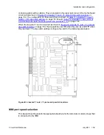
Daisy-chaining to MMI
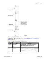
If two or more Lineside T1 cards are installed and the MMI is used, daisy-chain the cards
together to use one MMI terminal or modem, See
Figure 31: Lineside T1 card - connecting two
on page 170. Make the selection for this dip switch position based
on how many Lineside T1 cards are installed.
MMI master or slave
This setting is used only if daisy-chaining the cards to the MMI terminal or modem. This setting
determines whether this card is a master or a slave in the MMI daisy-chain. Select the master
setting if this card is the card that is cabled directly into the MMI terminal or modem; select the
slave setting if this card is cabled to another Lineside T1 card in a daisy chain.
Table 71: Lineside T1 card-T1 Switch 1 (S1) dip switch settings
on page 161 through
74: Lineside T1 card - CPE or CSU distance dip switch settings (Switch S2, positions 3 - 5)
page 163 describes the proper dip switch settings for each type of T1 link. After the card is
installed, the MMI displays the DIP switch settings the command
Display Configuration
QPC43 Peripheral Signaling card
on page 109 for details on how to invoke this
command.
Table 71: Lineside T1 card-T1 Switch 1 (S1) dip switch settings
Dip Switch
Number
Characteristic
Selection
1
MMI port speed selection
On = 1200 baud
Off = 2400 baud
2
T1 signaling
On = Ground start
Off = Loop start
3–6
XPEC Address for the Lineside T1 card
See
card - XPEC address dip
switch settings (Switch
Installation and configuration
Circuit Card Reference
July 2011 161
Содержание 1000 Series
Страница 1: ...Circuit Card Reference Nortel Communication Server 1000 7 0 NN43001 311 04 04 July 2011 ...
Страница 20: ...20 Circuit Card Reference July 2011 ...
Страница 30: ...Introduction 30 Circuit Card Reference July 2011 Comments infodev avaya com ...
Страница 116: ...Option settings 116 Circuit Card Reference July 2011 Comments infodev avaya com ...
Страница 140: ...NT1R20 Off Premise Station Analog Line card 140 Circuit Card Reference July 2011 Comments infodev avaya com ...
Страница 143: ...Figure 25 CP PIV card front Physical description Circuit Card Reference July 2011 143 ...
Страница 148: ...NT4N39AA CP Pentium IV Card 148 Circuit Card Reference July 2011 Comments infodev avaya com ...
Страница 244: ...NT5D33 and NT5D34 Lineside E1 Interface cards 244 Circuit Card Reference July 2011 Comments infodev avaya com ...
Страница 252: ...NT5D60 80 81 CLASS Modem card XCMC 252 Circuit Card Reference July 2011 Comments infodev avaya com ...
Страница 269: ...Figure 79 DDP2 cable for systems with an I O panel Physical description Circuit Card Reference July 2011 269 ...
Страница 287: ...Figure 86 Clock Controller Option 3 Operation Circuit Card Reference July 2011 287 ...
Страница 292: ...NT5D97 Dual port DTI2 PRI2 card 292 Circuit Card Reference July 2011 Comments infodev avaya com ...
Страница 302: ...NT5K21 XMFC MFE card 302 Circuit Card Reference July 2011 Comments infodev avaya com ...
Страница 346: ...NT6D80 MSDL card 346 Circuit Card Reference July 2011 Comments infodev avaya com ...
Страница 353: ...Figure 96 NTDK16 DLC Functional description Circuit Card Reference July 2011 353 ...
Страница 361: ...Figure 98 Digital line card jumper block and switch locations Configuration Circuit Card Reference July 2011 361 ...
Страница 362: ...NT8D02 and NTDK16 Digital Line cards 362 Circuit Card Reference July 2011 Comments infodev avaya com ...
Страница 378: ...NT8D09 Analog Message Waiting Line card 378 Circuit Card Reference July 2011 Comments infodev avaya com ...
Страница 393: ...Figure 111 Ground start call states outgoing call to CO FX WATS Operation Circuit Card Reference July 2011 393 ...
Страница 461: ...Figure 147 Paging trunk operation Applications Circuit Card Reference July 2011 461 ...
Страница 462: ...NT8D15 E and M Trunk card 462 Circuit Card Reference July 2011 Comments infodev avaya com ...
Страница 500: ...NTAK09 1 5 Mb DTI PRI card 500 Circuit Card Reference July 2011 Comments infodev avaya com ...
Страница 512: ...NTAK10 2 0 Mb DTI card 512 Circuit Card Reference July 2011 Comments infodev avaya com ...
Страница 534: ...NTAK79 2 0 Mb PRI card 534 Circuit Card Reference July 2011 Comments infodev avaya com ...
Страница 550: ...NTBK22 MISP card 550 Circuit Card Reference July 2011 Comments infodev avaya com ...
Страница 560: ...NTBK50 2 0 Mb PRI card 560 Circuit Card Reference July 2011 Comments infodev avaya com ...
Страница 566: ...NTBK51 Downloadable D channel Handler daughterboard 566 Circuit Card Reference July 2011 Comments infodev avaya com ...
Страница 584: ...NTCK16 Generic Central Office Trunk cards 584 Circuit Card Reference July 2011 Comments infodev avaya com ...
Страница 595: ...Figure 165 MGC block diagram Introduction Circuit Card Reference July 2011 595 ...
Страница 616: ...NTDW56 and NTDW59 Common Processor Media Gateway card 616 Circuit Card Reference July 2011 Comments infodev avaya com ...
Страница 642: ...NTDW61 and NTDW66 Common Processor Pentium Mobile Card 642 Circuit Card Reference July 2011 Comments infodev avaya com ...
Страница 662: ...NTRB21 DTI PRI DCH TMDI card 662 Circuit Card Reference July 2011 Comments infodev avaya com ...
Страница 668: ...NTVQ01xx Media Card 668 Circuit Card Reference July 2011 Comments infodev avaya com ...
Страница 676: ...NTC314AAE6 Media Gateway utility card 676 Circuit Card Reference July 2011 Comments infodev avaya com ...
Страница 700: ......