background image

REV-SA01 User

’s Manual 

REV-SA01  User

’s  Manual 


25 


3.4 Use MfgTool to flash Ubuntu into onboard eMMC   

Manufacturing tool, a successor of ATK, provides a series of new features to power your 

mass production work. The features like windows style GUI, multiple devices support, 

explicit status monitoring, versatile functionalities and highly flexible architecture make it a 

best choice to meet your critical timing, cost and customization requirements. 

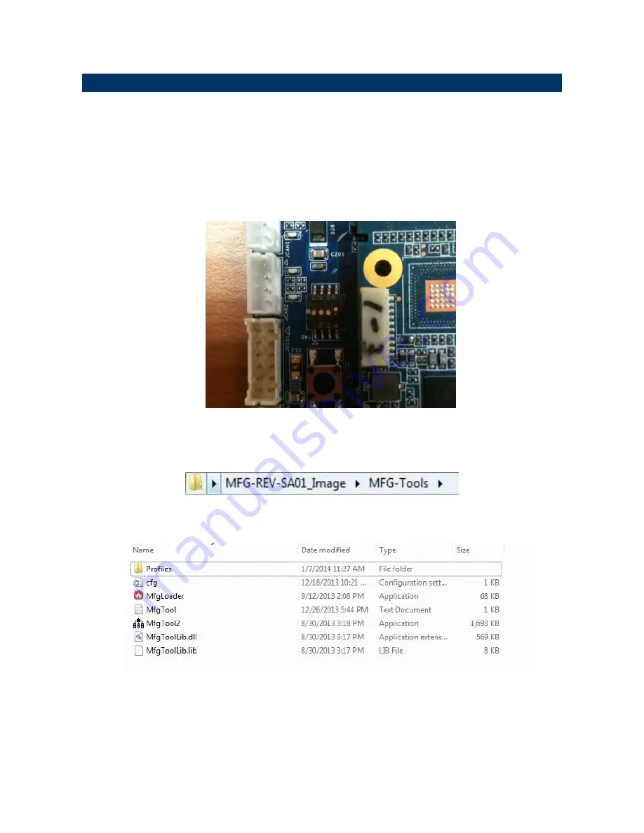
For using Mfgtool to flash image file into onboard eMMC, please follow up the steps below 


1.  Please turn on the 

Pin4

 of the DIP switch as below into burning mode of Mfgtool. 


2.  Power on the mainboard then plug the cable from OTG socket to PC. 

3. 

Click the folder “~\

MFG-Tools

”, e.g. mine is   

D:\


MFG-REV-SA01_Image\MFG-

Tools” 


4. 

Click the “

MfgLoader.exe

”. 


Содержание REV-SA01

Страница 1: ...Part No E2047VS0101R REV SA01 SMARC Evaluation Carrrier Board User s Manual 2nd Ed 16 October 2014...

Страница 2: ...nnector 1 JCAN1 18 2 3 8 Can Bus connector 2 JCAN2 18 2 3 9 LCD inverter connector JBKL1 19 2 3 10 AMPLIFIER connector JAMP1 19 2 3 11 Line In MIC connector JMIC1 20 2 3 12 USB connector JUSB1 20 2 3...

Страница 3: ...REV SA01 User s Manual REV SA01 User s Manual 3 3 11 Building up Andrioid image file 38 3 12 Use MfgTool to flash Android into onboard eMMC 40...

Страница 4: ...ronic devices are very sensitive to static electric charges As a safety precaution use a grounding wrist strap at all times Place all electronic components in a static dissipative surface or static sh...

Страница 5: ...REV SA01 User s Manual REV SA01 User s Manual 5 1 3 Document Amendment History Revision Date By Comment 1st December 2013 Avalue Initial Release 2nd October 2014 Avalue Update Linux User Guide...

Страница 6: ...fully before attempting to set up REV SA01 series or change the standard configurations Whilst all the necessary information is available in this manual we would recommend that unless you are confiden...

Страница 7: ...JA1041 GPIO 10bit GPIO pin header Audio connector Speaker out L R USB USB Type A double deck x 1 USB signal for mPCIe x1 USB 2 0 pin header x1 Mini USB connector for USB OTG SATA SATA connector x 1 2p...

Страница 8: ...REV SA01 User s Manual 8 REV SA01 User s Manual 1 6 Architecture Overview Block Diagram The following block diagram shows the architecture and main components of REV SA01...

Страница 9: ...REV SA01 User s Manual REV SA01 User s Manual 9 2 Hardware Configuration...

Страница 10: ...REV SA01 User s Manual 10 REV SA01 User s Manual 2 1 Product Overview...

Страница 11: ...REV SA01 User s Manual REV SA01 User s Manual 11...

Страница 12: ...al devices such as hard disk drives a keyboard or floppy drives In addition the board has a number of jumpers that allow you to configure your system to suit your application If you have any doubts ab...

Страница 13: ..._5P COM1 Serial Port 1 connector JCOM2 Serial Port 2 connector 2 x 6 wafer pitch 2 00mm HDMI1 HDMI connector HDMI_19P JLVDS1 LVDS Interface connector 20 x 2 wafer pitch 1 25mm PWR1 Power connector 2 x...

Страница 14: ...3 Setting Jumpers Connectors 2 3 1 Boot Mode selector SW1 Signal PIN PIN Signal GND 1 8 BOOT_SEL0 GND 2 7 BOOT_SEL1 GND 3 6 BOOT_SEL2 GND 4 5 FORCE_RECOV Booting from onboard eMMC Boot from SD card MF...

Страница 15: ...REV SA01 User s Manual REV SA01 User s Manual 15 2 3 2 General purpose I O Power selector JDIOP1 5V 3 3V 2 3 3 Battery connector JBAT1 Signal PIN V_BAT 1 GND 2...

Страница 16: ...4 General purpose I O connector JDIO1 Signal PIN PIN Signal DIO_GP10 1 2 DIO_GP20 DIO_GP11 3 4 DIO_GP21 DIO_GP12 5 6 DIO_GP22 DIO_GP13 7 8 DIO_GP23 SMB_DATA_9555 9 10 SMB_CLK_9555 VDIO 11 12 GND 2 3...

Страница 17: ...ignal 5V 2 1 3 3V 5V 4 3 3 3V I2C_LCD_DAT 6 5 I2C_LCD_CK GND 8 7 GND LVDS0 10 9 LVDS1 LVDS0 12 11 LVDS1 GND 14 13 GND LVDS2 16 15 LVDS3 LVDS2 18 17 LVDS3 GND 20 19 GND NC 22 21 NC NC 24 23 NC GND 26 2...

Страница 18: ...REV SA01 User s Manual 18 REV SA01 User s Manual 2 3 7 Can Bus connector 1 JCAN1 Signal PIN CAN0_H 1 GND 2 CAN0_L 3 GND 4 2 3 8 Can Bus connector 2 JCAN2 Signal PIN CAN1_H 1 GND 2 CAN1_L 3 GND 4...

Страница 19: ...ser s Manual REV SA01 User s Manual 19 2 3 9 LCD inverter connector JBKL1 Signal PIN NC 1 GND 2 LCD_BKLT_EN 3 LCD_BKLT_PWM 4 5V 5 2 3 10 AMPLIFIER connector JAMP1 Signal PIN SPKL_P 1 SPKL_N 2 SPKR_P 3...

Страница 20: ...A01 User s Manual 20 REV SA01 User s Manual 2 3 11 Line In MIC connector JMIC1 Signal PIN MICIN_DET 1 MIC_RAW 2 MICBIAS2_RAW 3 GND 4 2 3 12 USB connector JUSB1 Signal PIN 4V 1 USB3_D 2 USB3_D 3 GND 4...

Страница 21: ...Manual 21 2 3 13 Power connector PWR1 Signal PIN PIN Signal RVSP_G 1 2 RVSP_G VIN 3 4 VIN 2 3 14 Serial Port 2 connector JCOM2 Signal PIN PIN Signal RXDD3 1 2 RXDD2 TXDD3 3 4 TXDD2 GND 5 6 GND CTS3 7...

Страница 22: ...REV SA01 User s Manual 22 REV SA01 User s Manual 3 Linux User Guide...

Страница 23: ...currently supported and may have built issues Install host packages needed by building code This document assumes you are using Ubuntu Not a requirement but the packages may be named differently and t...

Страница 24: ...You can find the u boot u boot bin Kernel uImage under folder core as below after the compiling is finish PS If you would like to use Mfgtool for flashing image file you must put the file u boot bin a...

Страница 25: ...oring versatile functionalities and highly flexible architecture make it a best choice to meet your critical timing cost and customization requirements For using Mfgtool to flash image file into onboa...

Страница 26: ...ng then click Run MFG Tool Or the if the MCU of module board is i MX6 Quad core please click MX6Q Linux Update and click Linux ubuntu Ubuntu GUI version for the OS of flashing then click Run MFG Tool...

Страница 27: ...User s Manual 27 7 Click Start to flash image file 8 It will show Done after flashing is finish then click Stop and Exit to close the screen 9 You can also get the information from Terminal debug por...

Страница 28: ...space for the kernel the boot loader and its configuration data enter using the default value will create a partition that spans to the last sector of the medium w this writes the partition table to t...

Страница 29: ...9 sudo umount dev sdd1 sudo mount dev sdd1 mnt cd mnt sudo tar jxvpf ubuntu tar bz2 cd sudo umount dev sdd1 The Ubuntu file system content is now on the SD card You can insert it to mainboard then tur...

Страница 30: ...switch as below for booting from SD card 2 Insert SD card on SD socket Connect RS232 cross over cable from COM1 of mianboard to COM port of Host PC 3 Run hyper terminal program on Host PC teraterm on...

Страница 31: ...vice as below SMARC U Boot setenv linux_cmd setenv bootargs linux_bootargs mmc dev 1 mmc read loadaddr 0x800 0x3000 bootm SMARC U Boot setenv linux_bootargs console tty0 console ttymxc0 115200 root de...

Страница 32: ...D socket Connect RS232 cross over cable from COM1 of mianboard to COM port of Host PC 3 Run hyper terminal program on Host PC teraterm on Windows or minicom on Linux 4 Power on mainboard and press spa...

Страница 33: ...REV SA01 User s Manual REV SA01 User s Manual 33 SMARC U Boot setenv linux_bootargs console tty0 console ttymxc0 115200 root dev mmcblk0p1 rootwait rw SMARC U Boot saveenv SMARC U Boot boot...

Страница 34: ...of IMX6 module 1 You can find the file of resolution setup of LVDS VGA under the directory core kernel drivers video mxc for LVDS is ldb c and for VGA is mxc_lcdif c ldb c mxc_lcdif c 2 You need to f...

Страница 35: ...de configs Please add video mxcfb0 dev display name on the column 132 rootwait rw 0 to enable display output function when booting 4 Please refer ch1 3 to re build the u boot Kernel binary file for bo...

Страница 36: ...s Manual video mxcfb1 dev second display neme to mx6_smarc h but for this application you also need to write a program for controling the second diplay first or the second display will not enable aft...

Страница 37: ...his document assumes you are using Ubuntu Not a requirement but the packages may be named differently and the method of installing them may be different 1 Please follow up the commands below to instal...

Страница 38: ...er Android then start to compile image file 2 Type the command to compile image file run sh j16 j number means multi jobs for more efficiant building you can add it according to your CPU performance o...

Страница 39: ...EV SA01 User s Manual 39 PS If you would like to use Mfgtool for flashing image file you must put all the files u boot 6q bin u boot 6solo bin system img recover img boot img under Image smarc android...

Страница 40: ...t and customization requirements For using Mfgtool to flash image file into onboard eMMC please follow up the steps below 1 Please turn on the Pin4 of the DIP switch as below into burning mode of Mfgt...

Страница 41: ...Manual REV SA01 User s Manual 41 4 Click MfgTool2 exe to flash image file into smarc module 5 Click Start to flash image file 6 It will show Done after flashing is finish then click Stop and Exit to c...

Страница 42: ...REV SA01 User s Manual 42 REV SA01 User s Manual 7 You can also get the information from Terminal debug port COM1 after flashing is finish...

Отзывы: