


ENX-CDD User
’s Manual
38 ENX-CDD User
’s Manual
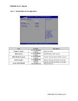
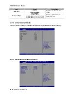
3.6.3.1 Host bridge
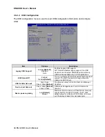
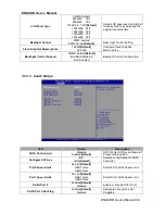
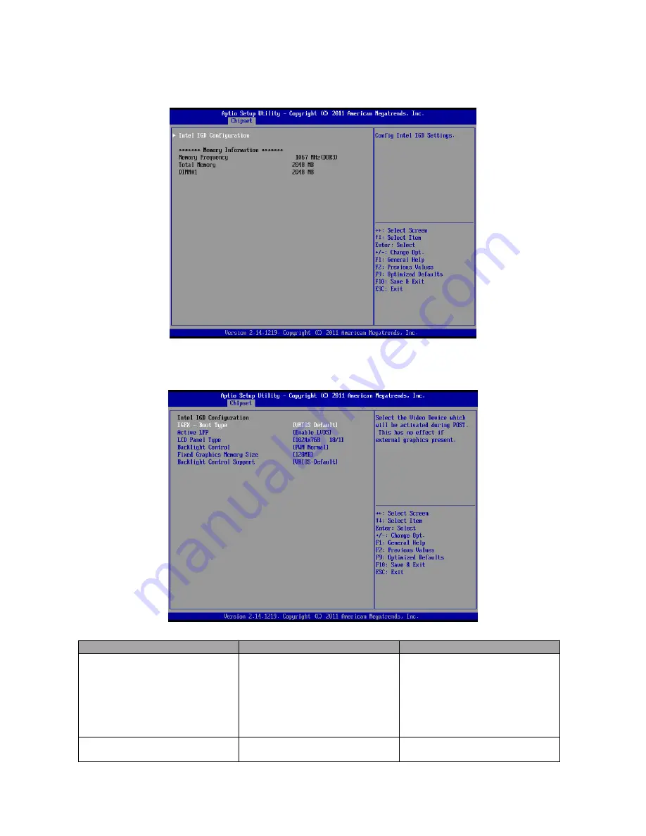
3.6.3.1.1 Intel IGD Configuration
Item
Option
Description
IGFX
– Boot Type
VBIOS Default
[Default]
CRT
LFP
EFP
CRT+LFP
CRT+EFP
LFP+EFP
Select the Video Device which will
be activated during POST. This
has no effect if external graphics
present.
Active LFP
Disabled
Enable LVDS
[Default]
Enable or Disable LVDS.
Содержание ENX-CDD
Страница 10: ...ENX CDD User s Manual 10 ENX CDD User s Manual 2 Hardware Configuration ...
Страница 11: ...ENX CDD User s Manual ENX CDD User s Manual 11 2 1 Product Overview ...
Страница 12: ...ENX CDD User s Manual 12 ENX CDD User s Manual ...
Страница 25: ...ENX CDD User s Manual ENX CDD User s Manual 25 3 BIOS Setup ...
Страница 52: ...ENX CDD User s Manual 52 ENX CDD User s Manual 5 Mechanical Drawing ...
Страница 53: ...ENX CDD User s Manual ENX CDD User s Manual 53 Unit mm ...
Страница 54: ...ENX CDD User s Manual 54 ENX CDD User s Manual Unit mm ...


