background image

4.0     CONNECTING THE HARDWARE 
 

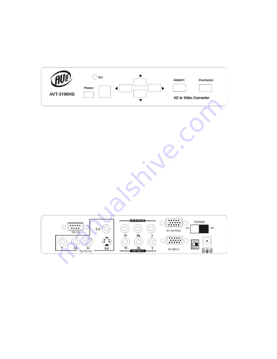
Please study the drawings below and become familiar with the inputs, outputs 
and control locations on the AVT-3190HD. 


AVT-3190HD Front Panel 


The Power Button switches between “Standby” and “On”. When the unit is turned 
on, the LED marked “On” above and slightly to the right of the power switch will 
illuminate. 
 
The Square window area to the right of the power switch is the location of the 
Infrared sensor used by the remote to control the unit. It must remain unblocked 
if the Remote IR unit is used to control the unit. 
 
The Four buttons with the arrows are used to position and pan the image. The 
Aspect button allows switching between wide screen and standard display 
modes and the Overscan button allows magnification of the image. 


AVT-3190HD Rear Panel 

 
The inputs and outputs on the rear panel are clearly marked. Connect the 
appropriate cables to the inputs making certain that the cables are in good 
condition and undamaged. The power switch (Upper right on the drawing above) 
removes or applies power to the unit. If the switch is in “Off” position, the power 
switch on the front will have no effect since it is a Standby switch, not an actual 
power switch. The Switch next to the power connector is used to switch between 
PC input and HDTV input.  


8

Содержание AVT-3190HD

Страница 1: ...AV Toolbox Instruction Manual AVT 3190HD PC HDTV to Video Scan Converter ...

Страница 2: ...2 ...

Страница 3: ... 0 Introduction 4 2 0 Specifications 6 3 0 Package Contents 7 4 0 Connecting the Hardware 8 5 0 Operating The Unit 9 6 0 Troubleshooting 17 7 0 Limited Warranty 18 8 0 Regulatory Compliance 19 9 0 Contact Information 19 3 ...

Страница 4: ...use of this hardware or any direct or indirect consequential damages arising from its use It is the responsibility of the user of the hardware to check that it is suitable for his her requirements and that it is installed correctly All rights reserved No parts of this manual may be reproduced or transmitted by any form or means electronic or mechanical including photocopying recording or by any in...

Страница 5: ...e S Video or Component YCbCr Supports PC Inputs up to UXGA 1600x1200 60Hz Supports VGA Refresh Rates to 140Hz Supports HDTV Inputs up to 1080i Loop Thru Inputs Both PC and HDTV Adjustable Image Scaling Pan Position and Zoom 2D Flicker Filter Aspect Ratio Adjustment Test Functions Overscan Freeze Test Pattern and Magnifier Remote Control with OSD On Screen Display RS 232 Control is Fully Supported ...

Страница 6: ...utput Signal Characteristics Composite S Video NTSC or PAL Interlaced Component YCbCr Control Methods Local Push buttons on unit OSD Remote IR Remote Control w OSD RS 232 Mechanical Size H W D 2 x8 x6 50mmx204mmx155mm Weight Net 2 2 Lbs 1kg Warranty Limited Warranty 1 Year Parts and Labor Power Requirements External AC Adaptor 5 VDC 2A US UK or EURO AC Plug Regulatory Approvals AVT 3190 FCC CE AC ...

Страница 7: ... 15 VGA Cable 1x 3 RCA to 3 RCA Cable 1x RCA to RCA Component Cable 1x S Video to S Video Cable 1x IR Remote Control 1x Applications Software CD 1x Operations Manual Note Please retain the original packing material should the need ever arise to return the unit If you find any items are missing contact your reseller or AV Toolbox immediately Have the Model Number Serial Number and Invoice available...

Страница 8: ...the unit The Four buttons with the arrows are used to position and pan the image The Aspect button allows switching between wide screen and standard display modes and the Overscan button allows magnification of the image AVT 3190HD Rear Panel The inputs and outputs on the rear panel are clearly marked Connect the appropriate cables to the inputs making certain that the cables are in good condition...

Страница 9: ...control over its functions it is recommended that you take the time to discover where the various buttons are located on the remote by looking at the actual remote and comparing it to the diagram above Like the manual controls on the unit the labeling is clear for the majority of the functions and the unit s On Screen Display OSD will help clarify any confusion The pages that follow will magnify t...

Страница 10: ...CAN Toggles Between over scanned and under scanned normal image BUTTONS 1 9 When the Zoom button is pressed the picture is divided into nine zones Pressing one of the numbered buttons selects the portion of the image the zone you want to enlarge ZOOM Press the Zoom button to enlarge a section of the picture Press it again to return to normal image size 10 ...

Страница 11: ...de the arrow buttons set the degree of overscan POS PAN If the unit is in underscan mode pressing this button allows the user to position the under scanned image anywhere on the raster using the arrow buttons If the unit is in the overscan mode pressing this button allows the user to pan the over scanned image using the arrow buttons ZOOM As explained above this Button places the unit in the Zoom ...

Страница 12: ...uttons to become active and those buttons are used to make the actual adjustments V RESET Restores Factory default settings to the Contrast Brightness Color and Sharpness parameters NTSC PAL Selects the television standard to use on the unit s output SYS RESET Restores Factory Presets to all parameters Overscan NTSC 4 3 Aspect Signal Parameters CV SV Output COLORBAR Causes an internally generated ...

Страница 13: ...reboot after the initial setup has finished If this happens reboot and run setup a second time Once fully installed click the taskbar menu Start Programs Scan Converter to start the RS 232 software 5 2 Operation Under Control of RS 232 Software A main panel will appear containing 19 icons that provide the control functions of the unit except icons 16 through 19 Click the icon to perform the functi...

Страница 14: ...t 13 Screen Freeze 14 Video Settings 15 RS 232 Com Port in use 16 Close 17 Minimize 18 System Tray 19 About Selecting Zoom will cause a sub menu to appear where the actual adjustments are made The functionality is just like the remote control for the sub panel wherein the arrows and number matrix control the same things that the remote control did The upward facing arrow at the lower right returns...

Страница 15: ...s control the same things that the remote control did The upward facing arrow at the lower right returns you to the main menu Selecting Video Settings on the main menu will call up another sub panel where the actual adjustment can be made Clicking the R icon on this panel resets these settings to Factory Default Again the upward facing arrow at the lower right returns you to the main menu 15 ...

Страница 16: ...s the image 1 5 times Selecting 2 0 results in a 2X magnification Clicking S generates an undersize image and B yields a Big frame The two intertwined arrows call up an image refresh routine and the X closes this sub panel There are two other sub panels available Clicking Option causes the following sub panel to appear Click on the desired action 16 ...

Страница 17: ...her than checking for faulty cables the only common problem would be choosing a wrong Output Setting Make sure the AVT 3190HD is capable of handling the resolution and refresh rate selected and make sure the output format selected Composite S Video or YCbCr is correct for the type of cable and connector being used at the output Also make certain that you have selected the correct television standa...

Страница 18: ...offered by the respective manufacturers Such specific warranties are available upon request to AV Toolbox If repairs are necessary under this warranty policy the original purchaser must obtain a Return Authorization Number from AV Toolbox and return the product to a location designated by AV Toolbox freight prepaid After repairs are complete the product will be returned freight prepaid LIMITATIONS...

Страница 19: ... Adaptor Supply has been tested for compliance with UL CSA and CE standards 9 0 CONTACT INFORMATION Should you have questions or require assistance with this product in areas not covered by this manual please contact us at the location shown below AV Toolbox 1350 Jamike Drive Erlanger Ky 41018 859 282 7303 19 ...

Страница 20: ...AV Toolbox 1350 Jamike Drive Erlanger Ky 41018 859 282 7303 ...

Отзывы: