33
UK
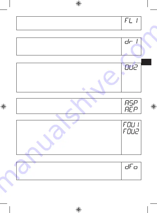
► Select [FL1] and set the lower limit of the acceptable range�
FL1 is always lower than FH1� The unit only accepts values which are lower
than the value for FH1�
10.5.4 Setting of the switch-off delay for OUT1
► Select [dr1] and set the value between 0�2 and 60 s�
At 0�0 (= factory setting) the delay time is not active�
The switch-off delay is only active if hysteresis has been set as switching
function (OU1 = Hno or Hnc)�
10.5.5 Setting of the output function for OUT2 (analogue output)
► Select [OU2] and set the output function:
[I] = current output 4���20 mA
[InEG] = current output 20���4 mA
[U] = voltage output 0���10 V
[UnEG]= voltage output 0���10 V
10.5.6 Scale the analogue signal
► Select [ASP] and set the analogue start point (→ 5.2.3)
► Select [AEP] and set the analogue end point (→ 5.2.3).
10.5.7 Response of the outputs in case of a fault
► Select [FOU1] / [FOU2] and set the value:
-[on] = output switches ON in case of a fault�
Analogue output switches on 20 mA / 10 V in case of a fault�
-[OFF] = switching output switches OFF in case of a fault�
Analogue output switches on 4 mA / 0 V in case of a fault�
Factory setting: [FOU1] and [FOU2] = [OFF]�
Faults: faulty hardware, too low a signal quality, untypical level curve�
Overflow is not considered to be a fault!
10.5.8 Setting of the delay time after signal loss
► Select [dFo] and set a value between 0�2 and 5�0 s�
At 0�0 (= factory setting) the delay time is not active�
Mind the dynamics of your application� In case of fast level changes it is
recommended to adapt the value step by step�


