-|Transparent Guide|-
Ordering Information
This is only for reference, the actual product does not support all combinations.
For selecting the specified model, follow the Autonics website.
Select a model that matches the ordering information of the motor and the driver.
AiCA
-
D
-
❶
❷
A
-
❸
-
EC
❶ Frame size
Number: Frame size (mm)
❸ Motor type
No mark: Standard type
B: Built-in brake type
❷ Axial length
M: Medium
L: Long
Cautions during Installation
•
Install on the metal plate with high thermal conductivity for heat
dissipation of the driver.
•
Install in the well-ventilated area and install the cooling fan in the
unventilated environment.
•
Failure to heat dissipation may result in damage or malfunction
due to the stress on the product.
Check the environment of use within the specifications and
install on the well-heat dissipated area
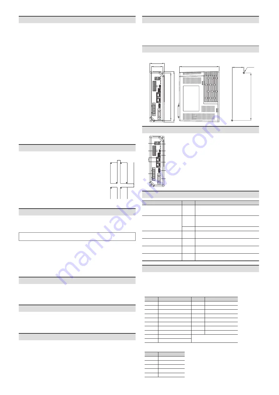
•
In case of installing the drivers more than two, keep distance at
least 20 mm in horizontal direction and at least 25 mm in vertical
direction.
Horizontal direction:
≥ 20 mm
Vertic
al dir
ec
tion:
≥ 25 mm
Manual
For proper use of the product, refer to the manuals and be sure to follow the safety
considerations in the manuals.
Download the manuals from the Autonics website.
Sold Separately
•
I/O cable: CO20-MP□-R (specifications: AiC-EC TAG)
•
Motor + Encoder cable: C1D14M(B)-□ (fixed type), C1DF14M(B)-□ (flexible type)
Product Components
• Product
• Instruction manual
• Power connector × 1
•
I/O connector × 1
•
Brake connector (AiCA-D-B-EC Series) × 1
Cautions during Use
•
Follow instructions in ‘Cautions during Use’.
Otherwise, it may cause unexpected accidents.
• Install vertically so that the status display part is located on top.
•
In case of unwanted noise generating from peripherals and power, use ferrite core in the
wiring.
•
The thickness of cable should be same or thicker than the below specifications when
connecting the cable for connector.
- Motor + Encoder connector: AWG22
- Power connector: AWG18
- I/O connector: AWG28
- Brake connector: AWG22
•
Keep the distance between power cable and signal cable over 10 cm.
•
Do not input external signal until the driver is initialized (In-Position LED ON) after power is
applied.
•
Motor vibration and noise may occur in a specific frequency range.
- Change the motor installation method or attach the damper.
- Use the unit out of the corresponding frequency range due to changing motor RUN speed.
•
Maintain and inspect regularly the following lists.
- Unwinding bolts and connection parts for the unit installation and load connection
- Abnormal sound from ball-bearing of the unit
- Damage and stress of lead cable of the unit
- Connection error with motor
- Inconsistency between the axis of motor output and the center, concentric (eccentric,
declination) of the load, etc.
•
This product does not contain a protection function for a motor unit.
•
This unit may be used in the following environments.
- Indoors (in the environment condition rated in ‘Specifications’)
- Altitude max. 2,000 m
- Pollution degree 2
- Installation category II
Unit Descriptions
09
06
07
05
03
04
01
08
02
10
01. Motor + Encoder connector
02. Power connector
03. Comm. connector
04.
I/O connector
05.
Brake connector (AiCA-D-B-EC Series)
06. USB connector
07.
Comm. ID setting rotary switch
08. Status display part
09. Status indicators
10. Comm. indicator
Dimensions
•
Unit: mm, For the detailed drawings, follow the Autonics website.
160
47
150
37
126
150
37
2-M5
Panel cut-out
Alarm / Warning
The status display part displays segment depending on Alarm / Warning type.
Depending on the alarm / warning type, it flashes for 0.4 sec interval and it turns OFF for 0.8 sec
repeatedly.
For more information of Alarm / Warning, refer to ‘User manual’.
■
Alarm
Display Alarm type
Display Alarm type
c5
EtherCAT comm. error
eA
Speed command error
e1
Overcurrent error
eB
Lack of voltage error
e2
Overspeed error
eC
In-Position error
e3
Position tracking error
eD
Memory error
e4
Overload error
eE
Emergency stop
e5
Overheat error
eH
Home search error
e6
Motor connection error
eJ
Brake connection error
e7
Encoder connection error
eK
PDO allocation error
e8
Overvoltage error
-
e9
Motor alignment error
■ Warning
Display Warning type
w1
+Software limit
w2
-Software limit
w3
+Hardware limit
w4
-Hardware limit
w5
Overload warning
Software
Download the installation file and the manuals from the Autonics website.
■
atMotion
The program allows to manage the motor driver's parameter setting and monitoring
data.
Status Display Part / Indicators
Display part / Indicator
Color
Descriptions
Status display part (7-segment)
Red
Displays EtherCAT ID
Displays the corresponding number, operation
when alarm / warning occurs
Power / Alarm indicator
(PWR/AL)
Green
Turns ON when the unit operates in normal after
power is applied
Flashes depending on the warning type
Red
Flashes depending on the alarm type
In-Position indicator (INP)
Yellow
Turns ON when motor is placed at command
position after positioning input
Servo ON / OFF indicator
(SERVO)
Blue
Turns ON when Servo ON, turns OFF when Servo
OFF
EtherCAT comm. error indicator
(ERR)
Red
Flashes depending on communication fail status
EtherCAT comm. operation
indicator
(RUN)
Green
Flashes depending on communication normal
status


