Page 8 of 26
7/9/19
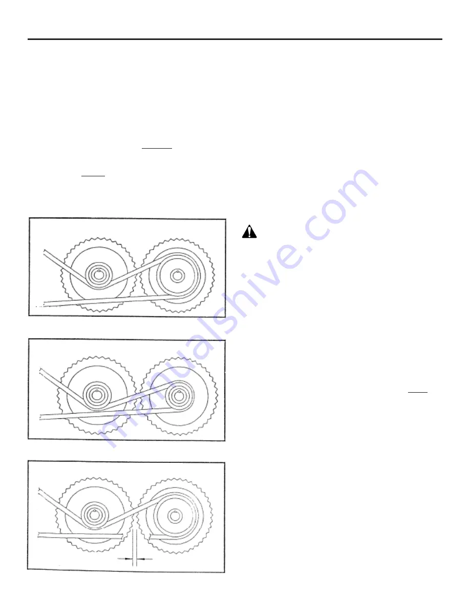
Figure 4
Figure 5
Figure 6
OPERATION / MAINTENANCE
OPTIONAL ROLL CONFIGURATION - This roller mill
is available with five different roll configurations and
comes standard with a differential drive (See Figure 4).
Corrugation numbers refer to the number of corrugations
or “teeth” per inch. The larger the corrugation number,
the smaller the particle size produced. Changing the roll
gap is the next preferred method for adjusting particle
size. (See Adjusting Rolls section, page 6) In addition,
feed consistency, or particle size, may be adjusted by
changing the relative drive roll and idler speeds. This
is accomplished by replacing the drive roll pulley with
a pulley the same size as that of the idler roll. (See
Figure 5). However, when the drive method is changed,
it will generally reduce the capacity of the mill and
not allow as fine a particle size. Consult your dealer, or
Automatic Equipment for recommendations regarding roll
configuration by any other method than those approved
by Automatic Equipment will void the warranty.
MAINTENANCE - Automatic roller mills are manufactured
from the best materials and workmanship available.
Simple adjustments and minimum maintenance have been
emphasized in their engineering. Although all components
of your roller mill are tested and properly adjusted
before it leaves the factory, some may require additional
adjustment after a break in period.
After your roller mill has been in operation for a few hours,
examine the entire machine for loose bolts, set screws,
lock collars, belts, etc. This initial check is an important
first step in an ongoing program for keeping your roller
mill in top running condition and should be performed
periodically as part of the general maintenance of your
roller mill. Like any other implement, your roller mill
requires proper care and intelligence in operation. Misuse
and/or neglect will only cause unnecessary expense and
dissatisfaction.
WARNING: SHIELDS AND GUARDS ARE PROVIDED
FOR YOUR PROTECTION. Although some shields and
guards may need to be removed or opened for servicing
and adjustments, they should always be replaced or
closed before operation resumes.
BELTS - All belts should be inspected for proper
alignment and tension after a few hours of operation.
Tension should be measured between the motor and flat
pulley. The belt should deflect 3/16” using approximately
60 pounds of force. Periodic checks of all belts should be
made to ensure proper alignment, correct tension levels
and to detect worn or deteriorating belts.
PULLEY SET SCREW ADJUSTMENT - The belt drive
system on your roller mill includes several pulleys which
use a setscrew to hold them in place on the key. ONLY
“Cup Point” set screws with knurled tips should be used.
To correctly seat the set screw, turn it “IN” and “OUT”
several times before tightening in place. This will wear a
groove in the key for the setscrew to seat in.
ROLLER TENSION SPRINGS - The roller tension springs
on the idler roll are set at the factory to maintain the
correct amount of pressure. They should be 4 1/2” long
±1/8”. The springs allow the rolls to separate so foreign
objects such as nails, bolts, stones, gravel, etc. may
pass between the rolls. A magnetic grate is standard
on the roller mill and should remove most of the metal
items, but in the event that something gets through, the
spring action will help prevent the roll teeth from being
damaged. If the rolls become out of alignment and require
readjustment, the springs may require similar adjustments.
(See Realigning Rolls, Page 8)
DIFFERENTIAL DRIVE
Idler (left)
SAME SPEED DRIVE
Idler (left)
ROLL SPACING
.015”
Idler (left)


