


NAM-TRS372-MT-EN-C
p25/38
The information in this document is the property of Automatic Systems and is confidential. The consignee withholds from using it for anything other than the use of the products or the execution of the
project to which they belong and withholds from communicating it to third parties without prior written agreement from Automatic Systems. Document subject to change without prior notice.
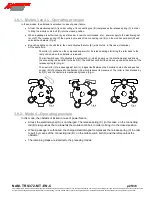
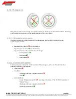
3.9.1. Modes 3 and 5 - Operating principle
In these modes, the obstacle is unlocked in case of power failure.
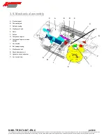
At rest, the electromagnet (A) is under voltage. Its connecting rod (B) compresses the release spring (C) in order
to bring the mobile comb bolt (D) into the closed position.
When a passage is authorized (by a card reader, a remote control desk, etc.), power supply to the electromagnet
is cut off. The release spring (C) then pulls, by means of the connecting rod (B), on the mobile comb bolt (D) and
unlocks the obstacle (
Fig.a
).
By pushing lightly on the obstacle, the user activates the rotor (E) (which turns, in this case, clockwise).
At the same time:
-
The roller (F) pushes on the compensating arm (G). Its release springs (H) bring the rotor back to the
rest position when the obstacle is released.
-
The limit switch cam (P) activates the limit switch (J), which powers up the electromagnet and drives
the connecting rod back (B) to the bolt (D). The mobile comb bolt then closes up under the action of the
release spring (K) (
Fig.b
).
-
The next roller (F) presses against bolt (L), lodges itself between the 2 mobile comb bolts and pushes
on cam (M) of hydraulic shock absorber (N), which reduces its movement. The roller is then blocked by
bolt (D), and the obstacle is mechanically locked (
Fig.c
).
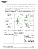
3.9.2. Mode 4
– Operating principle
In this mode, the obstacle is locked in case of power failure.
At rest, the electromagnet (A) is not charged. The release spring (C) (in this case, on the connecting
rod (B) side) pushes the rod towards the mobile comb bolt, in order to bring it in the closed position.
When a passage is authorized, the charged electromagnet compresses the release spring (C) in order
to pull, by means of the connecting rod (B), on the mobile comb bolt (D) and therefore unlock the
obstacle.
The remaining steps are identical to the preceding modes.
1
3
2
1
3
2
1
3
2
Fig. a
Fig. b
Fig. c


