


Revised 8/14/02 • U253
8
© 2002 Automated Logic Corporation
Refer to the section “Writing GFBs for the
U253” on page 9 for more information about
using a LogiStat sensor.
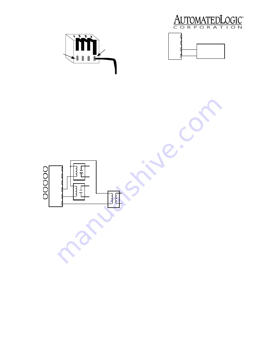
Digital Output Wiring
The U253 has two digital outputs that can be
connected to a maximum of 24 Volts AC/DC
(see Figure 9). Each output is a dry contact
(rated at 1A maximum) that is configured as
normally open.
Be sure the module’s power is off before
connecting any inputs or outputs.
To verify each output’s operation, lock the
output to a known condition using the
Function Block’s Properties page in WebCTRL
or the Parameter page in SuperVision, then
make sure the equipment operates as
specified.
Analog Output Wiring
The U253 has three analog outputs that
support voltage devices from 0 to 10VDC (see
Figure 10). The device being controlled must
have a minimum of 2000 Ohms resistance
measured from its input to ground and must
Be sure the U253’s power is off before wiring
any inputs or outputs. Connect the output
wiring to the screw terminals on the module.
To verify each output’s operation, lock the
output to a known condition on the Function
Block’s Properties page in WebCTRL or the
Parameter page in SuperVision, then make
sure the equipment operates as specified.
Using Flow Sensors
The U253 controls air flow in the zone using:
• a USF (single) air flow sensor and an
actuator connected to two digital
outputs
If you use a flow sensor with the U253, use
the Airflow microblock in the U253’s GFB.
To connect the sensor, make sure the U253’s
power is off first. Attach the total or high
pressure line from the VAV box to the
module’s HI side, and attach the static
pressure line to the module’s LO side.
Connect the USF to the U253 as shown in
Figure 11 on page 9.
To ensure an accurate reading from the flow
sensor, use the Airflow microblock in the
module’s GFB. You must calibrate this
microblock using the instructions on the FB’s
Properties page in WebCTRL or Parameter
page in SuperVision. Refer to the
Eikon for
WebCTRL Microblock Reference Guide
or the
Eikon Microblock Reference Guide
for more
information.
Figure 8. Flip Lever Wiring
Figure 9. Digital Output Wiring
2. Press black
tab down to
connect wire
1. Insert wire
into opening
DO
DO
BUSS
DO-1
DO-2
24VAC
Gnd
+
Figure 10. Analog Output Wiring
0 to 10V
+
-
Gnd
AO-1


