7
Rev. (30-JAN-98) • RLM v4.7
© 1995-98 Automated Logic Corporation
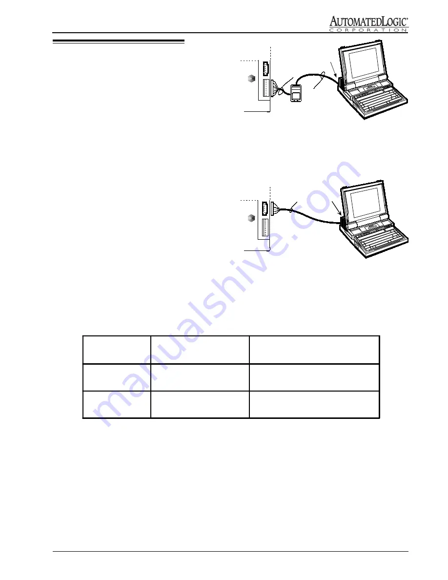
Figure 9: Connecting to the ZONE port
Local Access
The R683 allows you to connect a computer to the
ACCESS port or the ZONE port. You can connect to the
ZONE port either at the module or through an Enhanced
Zone Sensor (see Figure 9). The computer’s connection
type must be set to Direct Network.
The ZONE port uses an 8-pin connector. To make a cable
for this connection (see Figure 7), use ALC part no. CON,
a package of 8-wire connectors and covers (AMP part
no’s. 641237-8 and 640550-8) which require 22 AWG
stranded wire. Other connectors are available by calling
your local Amp distributor at 800-526-5142. The cable
wiring configuration is shown below. The cable should
not exceed 50 ft. See Figure 11 for how to use the
switches on the NI485 cable.
NOTE: When making a sensor cable, disregard the
numbers imprinted on the plastic connector.
The ACCESS port uses a 5-pin connector. To connect to
this port, use the NI485 cable head and the 235015 cable
(see Figure 10). See Figure 11 for how to use the switches
on the NI485 cable.
N I4 8 5
C a b l e
H e a d
2 3 5 0 1 5
C a b l e
R 6 8 3
ACCESS
ZONE
R S Z +
N I4 8 5
C a b l e
H e a d
R 6 8 3
ACCESS
ZONE
A L C
p a r t n o .
C O N
2 3 5 0 1 5
C a b l e
Figure 10: Connecting to the ACCESS port
Figure 11: NI485 Switch Table
NI485 Switch
Position
Module ACCESS Port
5 position
ZONE Sensor Port
8 position
Network
connected to module
connected to net
disconnected from the module
disconnected from the net
Isolated
connected to module
disconnected from net
connected to module
disconnected from net


