


Creating a Callout Tag
When creating a callout tag, you can specify the following:
■
The type of callout head to use. See
Creating a Callout Head Family
on page 151.
■
The radius of the callout bubble.
To specify the line weight, color, and style of the callout bubble or leader line, see
on page 153.
To create a callout tag
1
In a project, click Manage tab
➤
Project Settings panel
➤
Settings drop-down
➤
Callout Tags.
2
In the Type Properties dialog, for Callout Head, specify the type of callout head to use.
3
For Corner Radius, specify the radius of the corners for the callout bubble.
If your organization uses round callouts, set the radius to a large value.
4
Click OK.
Changing Display Properties for Callout Tags
You can control the line weight, color, and pattern used for callout bubbles and leader lines. The settings
that you specify here apply to all callouts in the project.
To change the line styles for callout bubbles and leader lines
1
In a project, click Manage tab
➤
Project Settings panel
➤
Settings drop-down
➤
Object Styles.
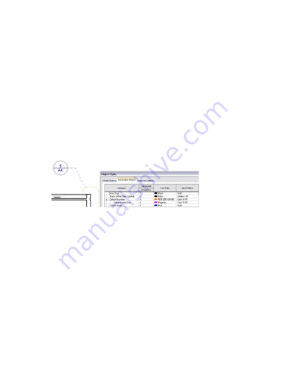
2
Click the Annotation Objects tab.
3
Under Category, expand Callout Boundary.
4
Use the Line Weight, Line Color, and Line Pattern columns to specify the desired settings for
callout boundaries, callout leader lines, and callout heads.
5
Click OK.
Visibility of Callouts
Revit Architecture offers several ways to control the visibility of callout bubbles in a view. If you cannot see
callout tags in a view as expected, check the following:
■
Visibility/Graphics setting
. Open the view in which you want to see the callout tag. Click View
tab
➤
Graphics panel
➤
Visibility/Graphics. On the Annotation Categories tab, under Visibility, make
sure that Callouts is selected. (To hide all callout tags in the view, clear this option.)
Visibility of Callouts | 153
Содержание 256B1-05A761-1301 - AutoCAD Revit Structure Suite 2010
Страница 1: ...Revit Architecture 2010 User s Guide March 2009 ...
Страница 4: ......
Страница 42: ...xlii ...
Страница 84: ...42 ...
Страница 126: ...84 ...
Страница 166: ...124 ...
Страница 229: ...Schedule Field Formatting Calculating Totals Specifying Schedule Properties 187 ...
Страница 230: ...Schedule with Grid Lines Schedule with Grid Lines and an Outline 188 Chapter 5 Project Views ...
Страница 304: ...262 ...
Страница 427: ...Defining the first scale vector Defining the second scale vector Resizing Graphically 385 ...
Страница 454: ...Before painting applying material to stairs 412 Chapter 8 Editing Elements ...
Страница 456: ...414 ...
Страница 486: ...444 ...
Страница 674: ...632 ...
Страница 802: ... Attachment Style Cut Column Attachment Justification Intersect Column Midline 760 Chapter 13 Architectural Design ...
Страница 809: ...Curtain wall Curtain Grid Curtain Walls Curtain Grids and Mullions 767 ...
Страница 994: ...952 ...
Страница 1016: ...974 ...
Страница 1204: ...1162 ...
Страница 1290: ...1248 ...
Страница 1318: ...1276 ...
Страница 1372: ...1330 ...
Страница 1382: ...1340 ...
Страница 1462: ...1420 ...
Страница 1492: ...1450 ...


