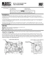
We recommend only an experienced technician perform this installation. Do NOT attempt, if you are unfamiliar with automotive wiring!
Carefully inspect the wiring at each of the coil packs and note the wire colors
at each coil. You will notice that one wire at each coil is different from one to
the next, and that one wire is the same color at every coil. The wire that is
the same at every coil is your coil power supply. Due to the nature in how the
Hemi is wired from the factory, you will need to cut the power wire in half at
each coil on both banks of coils. Be sure to leave enough wire at each coil
to splice onto later (about 2” works well). After you cut all 8 coil powers, use
a 16g wire and link all the power (harness side) cut halves together, then
hook to the solid red of the 9117 tachometer adapter. Next, use 16g wire
and link all the coil-side cut halves together and hook to the red wire with a
green stripe of the 9117 tachometer adapter. Ground the black 9117 adapter
wire. The gray wire is your new tachometer signal wire. Set your tachometer
as 8 cylinder (4 ppr). All connections should be properly soldered and heat
shrunk.
CLOSE-UP VIEW OF WIRING BEFORE INSTALLATION
TACH
ADAPTER
T
ACH
A
DAPTER
Model 9117
Sycamore, IL 60178
2511-737
RED
BLACK
RED/GRN
GRAY
CLOSE-UP VIEW OF WIRING AFTER INSTALLATION
Connecting to a Dodge Hemi with Coil per cylinder ignition.
Pin #34 may be Red,
Red/Green or White/Blue
depending on year
CLOSE-UP VIEW OF 42 PIN CONNECTOR.
(Position of Numbers May Vary)
TACH
ADAPTER
T
ACH
A
DAPTER
Model 9117
Sycamore, IL 60178
2511-737
BLACK
POWER SUPPLY FOR COILS
RED/GRN
RED
GRAY
TIP:
IT IS EASY TO TRACE THIS WIRE TO A PLACE ON THE PASSENGER SIDE FIREWALL WHERE IT IS EASY TO WORK WITH.
CUT HERE
CONNECT TO GREEN WIRE ON TACH, SHIFT-LITE, OR
DPSS CONTROLLER.


