en/TA-11-ALM-6040/10040FL
pag.: 24
USER /
INSTALATION
MANUAL
4-POST HD
ISSUED 26-05-04
A L M - 6 0 4 0 F L
A L M - 1 0 0 4 0 F L
AUTEC Hefbruggen bv
Industrieterrein IJsselveld, Vlasakker 11, 3417 XT MONTFOORT, The Netherlands
Tel: +31 348 477000 Fax: +31 348 475104 Internet: www.autec.nl - E-mail: [email protected]
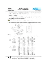
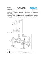
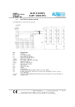
If the rise button
(22)
is pressed, the lift should go up (if not, see “WARNING” section). Check that the lift halts
by operating the upper limit switch
(24)
by hand. If the descent button
(23)
is pressed, the lift should descend.
Check that it stops by operating the lower limit switch
(25)
by hand. If not, invert the two phases in the switch
(21)
input terminals.
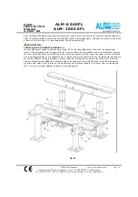
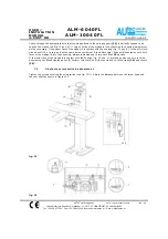
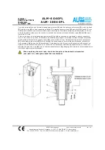
Allow the lift to descend to the lower stop and fasten the four counter plates
(26)
to the floor by means of
expansion nogs
(27)
(supplied with the lift), passing them through the diameter 25 holes in the counter plates.
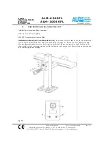
Then put the posts in upright position
(fig. 8)
. Loosen the screws
(28)
that fasten the adjustment device
(29)
.
Using a spirit level on the outside, back and side of each post, position the posts properly by tuming the adjust-
ment screws
(29)
as required. When all four posts have been mounted according the plumb line, fasten all the
screws
(28)
. We recommend checking the parallelism with a wire at the base and at the head of the posts.
A difference of 5 mm is accepted. Diagonals need no checking since the plugs
(15)
on the footboards are lixed.
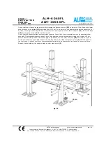
fig. 16
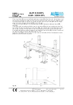
fig. 17


