8
9
15
6
11
14
9A
41
35
33
34
32
27
25
61
16
5
2
3
39
9B
9C
4
1
7
12
10
40
MODEL 341A
Figure 2. Model 341A Exploded View
Страница 1: ...ubricate the bearings at regu lar intervals using a grease of high quality Polyurea base Warning Electrical Shock Hazard All electrical connections are to be made by a qualified elec trician in accordance with all codes and ordinances Failure to follow these instructions could result in serious personal injury death or property damage Warning Electrical Overload Hazard Insure all motors have prope...
Страница 2: ... oil should be changed about once a year However when the pump is exposed to dirt contamination high temperatures 200 F or above or a wet location the oil may have to be changed every 2 to 3 months Use normal fire caution procedures when using any petroleum cleaner REPAIRS Before starting any work insure the electrical power is locked out the system pressure has been lowered to 0 psi and tempera t...
Страница 3: ...oved with a puller New ring s should be used for reassembly since it is likely that during removal this fit will be lost Do not remove wearing rings if not being replaced 9 Impeller wearing rings optional 14 and 15 are pressed on and must be cut off if replacement is necessary If they are turned off in a lathe take care not to cut into the impeller 10 Slide sleeve 25 with rotating parts of mechani...
Страница 4: ...s 48 Insert grease seals 51A and position slingers 47 and 47A on the shaft 344A 5 The mechanical seal 27 see Figure 1 cannot be installed as an assembly It is necessary to have the seal seat properly in place in bracket 35 before the balance of parts can be added Thoroughly inspect the seal cavity in seal bracket checking for burrs or nicks which could damage flexible cup of mechanical seal Apply ...
Страница 5: ... bracket and secure with screws 5 On Model 342A pumps position gasket 72 and set pump assembly in place Tighten pump to base 73 with capscrews 39 13 Replace all relief cooling flushings or drain lines from the pump including compression connections 1 and 2 and tub ing 3 Replace all grease fittings pipe plugs tube vents and oiler assembly for oil lubricated units Connect discharge piping and suctio...
Страница 6: ...FLEXIBLE CUP STATIONARY SEAT WASHER FLEXIBLE BELLOWS RETAINER DRIVE RING SPRING MODELS 341A 342A 344A 6 Figure 1 Mechanical Seal ...
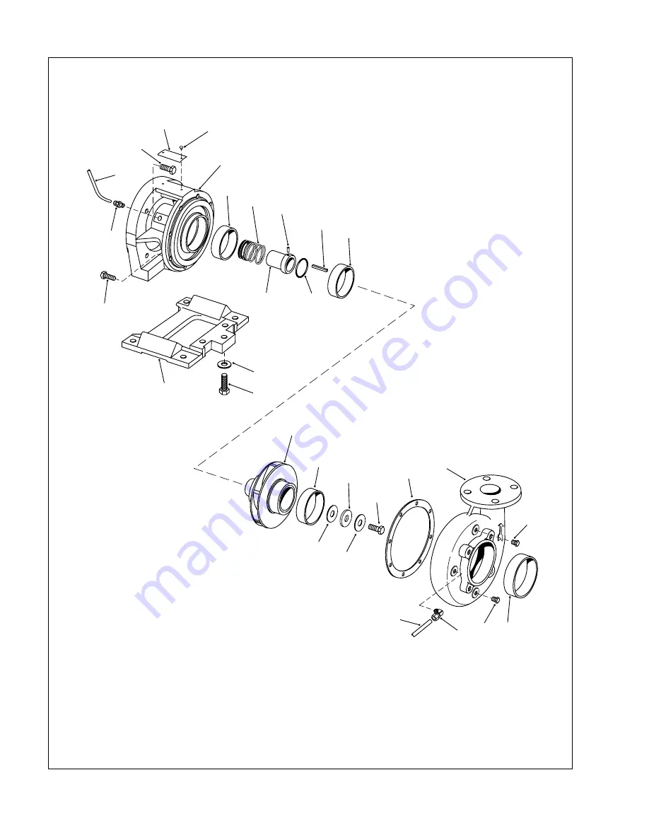
Страница 7: ...ar Ring 25 Sleeve 27 Seal 32 Capscrew 33 Screw 34 Nameplate 35 Bracket 39 Capscrew 40 Washer 41 Support 61 Pin 1 Elbow 2 Connector 3 Tubing 4 Plug Pipe 5 Capscrew 6 Casing 7 Wear Ring 8 Gasket 9 Impeller Screw 9A Washer MODEL 342A LIST OF PARTS 9B Gasket 9C Capscrew Seal 10 Gasket 11 Impeller 12 Impeller Key 14 Wear Ring 15 Wear Ring 16 Wear Ring 25 Sleeve 27 Seal 32 Capscrew 33 Screw 34 Nameplate...
Страница 8: ...8 8 9 15 6 11 14 9A 41 35 33 34 32 27 25 61 16 5 2 3 39 9B 9C 3 4 1 7 12 10 40 4 MODEL 341A Figure 2 Model 341A Exploded View ...
Страница 9: ...9 6 7 72 74 75 73 39 4 1 3 8 27 35 32 5 61 12 15 11 14 10 25 16 33 34 2 3 9B 9A 9C 9 4 MODEL 342A Figure 3 Model 342A Exploded View ...
Страница 10: ... 16 8 11 14 9A 9B 9C 7 15 27 25 61 12 10 49 52 50 55 42 54 57 64 2 3 5 35 63 62 39 60 33 46 56 51 47A 46 56 48 47 51A 53 41 40 44 59 58 59 9 6 1 3 4 34 32 4 59 43 Figure 4 Model 344A Exploded View AP Sect 6 Item 340 ...