37
8.2. Connectors
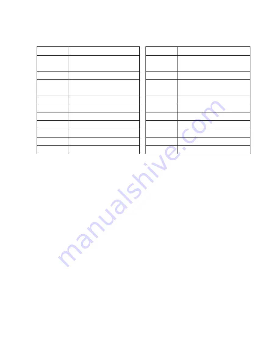
Connectors Function
Connectors Function
CN4
COM6 Connector
CN16
HDD Action LED Connector
CN5
Speaker & MIC Connector
CN17
LAN Action LED Connector
CN6
CD-in & Line-in Connector
CN18
Hardware Status Display
connector
CN7
USB8
CN19
LVDS (DVI)
CN9
Power Connector (+5V/+12V)
FAN_CPU3 CPU Fan Connector
CN10
Power Connector (+5V/+12V)
FAN_SYS3 System Fan Connector
CN11
Hardware Reset Connector
IDE3
Primary IDE Connector
CN12
Power Connector (+5V/+12V)
PWR3
+24V Power Output
CN13
Power Connector (+5V/+12V)
PWR5
+12V Connector
CN15
Power LED Connector
Содержание POSEO 5200
Страница 8: ...8 2 System View 2 1 Front View 2 x USB HDD Power Key Lock Power Button Hardware Status Display...
Страница 33: ...33 c c Remove the screws 7 d Remove the hex nuts 16 to release the motherboard from the chassis...
Страница 36: ...36 8 Jumper Settings 8 1 B99 Motherboard...
Страница 48: ...48 Appendix B Dimensional Drawings...


