


14
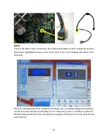
3.3. VFD Customer Display
a. Remove the screws (2) of the VFD
dummy door.
b. Slide the VFD dummy door out.
c. Remove the screws (2) of the CPU
RAM door.
d. Slide the CPU RAM door out.
e. Pass the VFD cable through the hole as
shown in the picture.
f. Click both sides of the VFD assembly
into the position as shown in the picture.
Содержание Odysse II
Страница 1: ...User Manual February 2011 Revision 1 0 ...
Страница 8: ...8 e Biometric Reader fingerprint f Customer Display VFD g 2nd Display ...
Страница 9: ...9 2 System View 2 1 Front Side view 2 2 Rear view ...
Страница 10: ...10 2 3 I O view ...
Страница 32: ...32 6 Jumper Settings 6 1 Main Board Layout ...
Страница 36: ...36 6 3 Connectors Location ...
Страница 44: ...44 Appendix B Dimensional Drawings All dimensions in mm ...
Страница 45: ...45 ...


