-10-
OPERATION
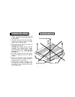
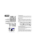
1
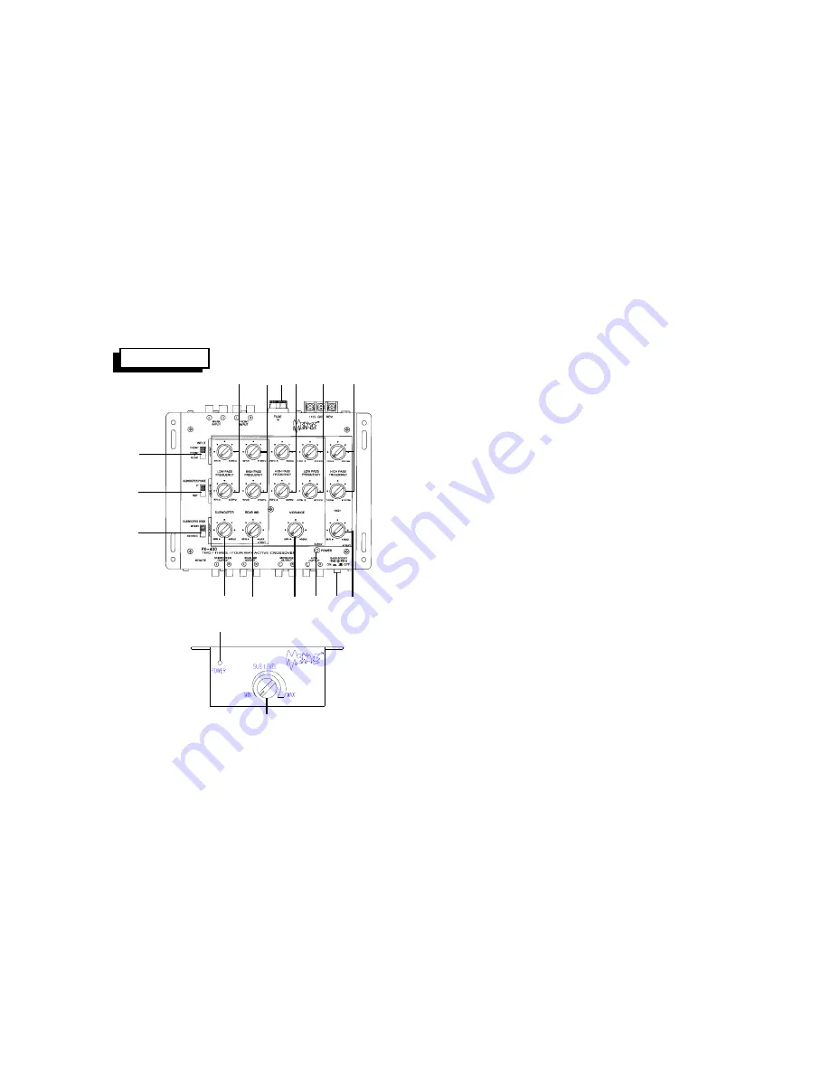
POWER INDICATORS
The Power Indicator LED’s on the crossover and the Remote Subwoofer
Level Control will illuminate to indicate that the unit is connected to the
battery and that the Remote Turn-On terminal is rec12 volts, thus
turning on the crossover.
2
INPUT SELECTOR
This switch is used to select the inputs of the audio signal to the
crossover. In the “FRONT” setting, only the input connected to the
“FRONT INPUT” jacks will be processed. In the “FRONT + REAR” setting,
both the inputs to the “FRONT INPUT” and “REAR INPUT” jacks will be
processed.
NOTE:
When set to the “FRONT + REAR” setting, the signal to the “REAR
INPUT” jacks is processed and adjusted by the Subwoofer Level
Control
6
, Subwoofer Low-Pass Frequency Controls
bl
, Rear
Midrange Level Control
7
, and Rear Midrange High-Pass
FrequencyControls
bm
. Thesignaltothe“FRONTINPUT”jacks is
processed by the Midrange Level Control
8
, Midrange High-Pass
FrequencyControls
bn
,MidrangeLow-PassControls
bo
, High
Level Control
9
, and High High-Pass frequency Controls
bp
.
3
SUBWOOFER PHASE SELECTOR
This switch is used to adjust the phase of the “SUBWOOFER OUTPUT”
by 180°. Set the switch to the position that provides the smoothest bass
response with the speaker system being used.
4
SUBWOOFER MODE SELECTOR
This switch is used to select Stereo or Mono subwoofer output. If the
speaker system uses 2 channels of low-frequency amplification and
2 woofers, set the switch to the “STEREO” position. If used with a single
channel of low-frequency amplification, set the switch to the “MONO” position.
2
b
m
bl
b
n
b
q
6 7
1
8
3
5
4
b
o
br
1
9
b
p


