


128-6992
7 of 8
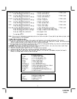
Second Turn the valet switch on then off
2 chirps = auto locks off
2 Flash pause
Press transmitter Lock button to change
1 chirp = auto locks on
or
Third
Turn the valet switch on then off
2 chirps = auto unlock off
3 Flash pause
Press transmitter Lock button to change
1 chirp = auto unlock on
or
Fourth
Turn the valet switch on then off
1 chirp = chirps on
4 Flash pause
Press transmitter Lock button to change
2 chirps = chirps off
or
Fifth
Turn the valet switch on then off
2 chirps = active locks
5 Flash pause
Press transmitter Lock button to change
1 chirp = passive locks
or
Sixth
Turn the valet switch on then off
2 chirp = horn output
6 Flash pause
Press transmitter Lock button to change
1 chirp = siren output
or
Seventh Turn the valet switch on then off
1 chirp = 800ms door lock output
7 Flash pause
Press transmitter Lock button to change
2 chirps = 3.5 second door lock output
Press transmitter lock button to change
3 chirps = 800ms lock dbl 800ms unlock
or
Press and release the valet switch
Exit program mode
or
Turn ignition key off
Exit program mode
Note:
Once you enter the feature programming mode, do not allow more than 15 seconds to pass between steps, or the
programming will be terminated.
COMPLETING THE INSTALLATION:
After you have confirmed the operation of the system, and tested any and all optional features of the system:
1. Mount the control module up and behind the dash securing it in place with cable ties or screws. Be certain that the
chosen mounting location will not inhibit any of the controls of the vehicle.
2. Securely harness and tie all wiring up and away from all hot and moving parts that they may come in contact with under
the dash board or in the engine compartment areas.
CAUTION:
Particularly avoid the area around the steering shaft and column, as wires can wrap around these
mechanisms and impair the safe operation of the vehicle.
3. Check the vehicle's wipers, lights, horn, etc... to insure proper operation.
4. Replace all panels that were removed during installation, and retest the system.
5. Explain the operation of the system and its various features to the end user if available and place the Owner's
Manual on the dashboard for them to find and review.
12 Pin Main Harness
White
(+) Parking Light Output
Red
(+) 12 V Constant Power 15A
Red/Purple
(+) 12 V Constant Power 5A
Green
(-) Door Trigger Input
Purple
(+) Door Trigger Input
Yellow
(+) 12 V Ignition Input
Brown/Black
(-) Horn Honk Output 300mA
Black/White
(-) Dome Light Supervision Output 300mA
Red/White
(-) Trunk Pop Output 300mA
White/Blue
(-) Latched Output 300mA (Ch 4)
Orange
(-) Ground When Armed Output 300mA
Black
(-) Chassis Ground
3 Pin Door Lock Harness
Green
(+) Unlock / (-) Lock
Blue
(+) Lock / (-) Unlock
Blue/Red
(-) 2nd Unlock
7


